
 English
 Spanish
 French
 German
 Italian
 Chinese (Simplified)
 Japanese
 Korean
 Arabic
 Portuguese
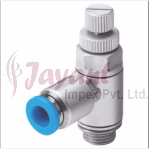


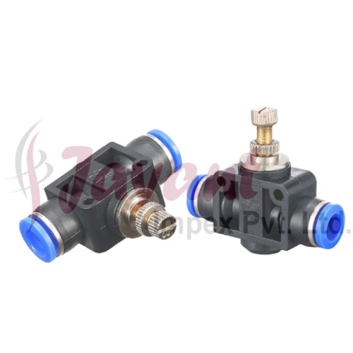

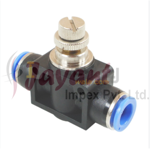
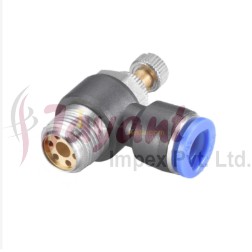

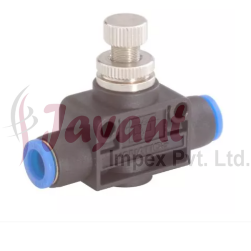
Pneumatic Flow Control Valve / Control Valves
6000.0 INR/Piece
Product Details:
- Valve Size Standard (customized options available)
- Connection Type BSP Threaded
- Control System Manual Adjustment
- Valve Type Pneumatic Control Valve
- Features Compact Design, Easy Installation, Leak-Proof
- Material Aluminium Body, Brass Component
- Voltage Not Applicable (Pneumatic)
- Click to view more
X
Pneumatic Flow Control Valve / Control Valves Price And Quantity
- 20 Piece
- 6000.0 INR/Piece
Pneumatic Flow Control Valve / Control Valves Product Specifications
- Air
- -5C to 60C
- Not Applicable (Pneumatic)
- Standard (customized options available)
- Flow Control Valve
- Pneumatic Control Valve
- 2 Pin
- Compact Design, Easy Installation, Leak-Proof
- Pneumatic
- Aluminium Body, Brass Component
- Fluid Flow Regulation, Pneumatic Systems
- 0.05 MPa to 1.2 MPa
- 1/4 BSP
- Straight Through
- BSP Threaded
- Manual Adjustment
- Brass
- NBR Rubber
- Manual Knob
- Fine to Full Open
- Anodized
- Male & Female options
- Over 1 Million Operations
- Uni-Directional
- Approx. 80 grams
- Inline
- ISO 5599/1
Product Description
A Pneumatic Flow Control Valve uses compressed air to precisely position a valve plug or disc, allowing it to regulate fluid pressure, temperature, or flow rate in a process line. Unlike standard manual or on/off valves, a pneumatic control valve acts as the "final control element" in a dynamic automation loop.
Here is an engineering overview of how these assemblies work, their core components, and how they function within industrial systems.
The Control Loop Assembly
A pneumatic control valve does not operate in a vacuum. It relies on a continuous feedback loop consisting of three main parts:
-
The Sensor/Transmitter: Measures the process variable (e.g., a flow meter measuring GPM).
-
The Controller (PLC/DCS): Compares the measured value to the desired setpoint and calculates the required correction.
-
The Control Valve: Receives the command signal and physically adjusts its opening to correct the flow.
Core Components of the Valve
A complete automated pneumatic control valve assembly consists of three primary elements:
[ Control Signal ] ---> [ Positioner ] ---> [ Pneumatic Actuator ] ---> [ Valve Body ]
1. The Pneumatic Actuator
The actuator converts air pressure into mechanical linear or rotary force to move the valve stem.
-
Diaphragm Actuators: The most common type for control valves. Compressed air pushes against a flexible rubber diaphragm, compressing a heavy-duty internal spring.
-
Air-to-Open (Fail-Closed): Air pressure pushes the stem down to open the valve; if air pressure is lost, the spring forces the valve shut.
-
Air-to-Close (Fail-Open): Air pressure forces the stem down to close the valve; if air is lost, the spring opens it.
-
-
Piston Actuators: Used when longer stem travel or higher thrust forces are required. They operate at higher air pressures than diaphragm actuators.
2. The Digital Positioner (I/P Transducer)
Because compressed air is compressible, simply sending a raw air signal doesn't guarantee precise valve positioning. A smart positioner solves this.
-
It receives an electrical control signal (typically 420mA or a digital bus protocol like HART or Profibus).
-
It monitors the valve stems actual position via a feedback linkage.
-
It dynamically adjusts the internal pneumatic instrument air supply to the actuator until the physical position matches the control signal perfectly.
3. The Valve Body and Trim
The body contains the fluid pressure, while the "trim" refers to the internal components that directly modulate the flow.
-
Globe Valves: The industry standard for precise throttling control. The stem moves linearly, lifting a plug out of a matched seat. They handle high pressure drops well but have higher flow restriction.
-
Segmented Ball / V-Port Valves: A rotary option where the ball has a V-shaped notch. As it rotates, the geometry allows for an inherently equal-percentage flow characteristic, making it excellent for high-capacity flow control or handling slurries.
-
Butterfly Valves: Used for high-flow, low-pressure drop control in larger line sizes.
Flow Characteristics
Control valve trims are specifically machined to alter flow rates predictably based on stem travel. The three main inherent flow characteristics are:
-
Linear: Flow rate is directly proportional to valve travel (e.g., at 50% open, you get 50% of maximum flow). Ideal for liquid level control.
-
Equal Percentage: Equal increments of valve travel produce equal percentage changes in the existing flow. (e.g., moving from 20% to 30% open increases flow by the same percentage as moving from 70% to 80%). This is the most common choice for pressure or temperature control loops where dynamic system pressure variations occur.
-
Quick Opening: Provides large flow changes at the very beginning of the stroke. Typically reserved for on/off safety isolation or relief systems rather than tight throttling modulation.
Key Engineering Selection Criteria
| Parameter | Specification Considerations |
| Flow Coefficient ($C_v$) | Calculated based on flow rate, fluid density, and allowable pressure drop ($Delta P$). An oversized valve causes control instability; an undersized valve restricts process capacity. |
| Choked Flow & Cavitation | High pressure drops across liquid control valves can cause vaporization and subsequent bubble collapse (cavitation), destroying trim components. Anti-cavitation multi-hole trims must be specified in these scenarios. |
| Shutoff Class | Defined by ANSI/FCI 70-2. Ranges from Class II (general control, higher leakage allowed) to Class VI (resilient soft seats providing bubble-tight isolation). |
| Material Standards | Common body casings include cast carbon steel (ASTM A216 WCB), stainless steel (ASTM A351 CF8M), or chrome-moly steels for high-temperature steam lines. |
Precision Flow Regulation
This control valve features a manual knob and uni-directional design, enabling smooth and accurate adjustment of pneumatic air flow. The fine-to-full open adjustment range offers precise control, enhancing efficiency and performance in various fluid regulation tasks.
Rugged and Leak-Proof Construction
Made with an anodized aluminium body and brass components, the flow control valve resists corrosion and wear. Its leak-proof design, NBR rubber sealing, and durability through over one million cycles guarantee long-lasting, reliable operation even in demanding environments.
Flexible Installation and Application
With a straight-through structure and compact dimensions, the valve easily fits into pneumatic systems via BSP threaded end connections, available in both male and female options. It meets ISO standards and suits fluid regulation applications in industrial and commercial setups.
FAQ's of Pneumatic Flow Control Valve / Control Valves:
Q: How do you adjust the airflow using the pneumatic flow control valve?
A: The valve comes with a manual knob that allows for gradual, precise adjustment of airflow. Simply turn the knob to control the opening-ranging from fine regulation to fully open-tailoring the flow according to your system's requirements.Q: What applications is this flow control valve suitable for?
A: This valve is ideal for fluid flow regulation in pneumatic systems found in manufacturing, industrial automation, and process equipment. It is commonly employed by dealers, exporters, fabricators, and other professionals managing pneumatic air lines.Q: When should the flow control valve be installed inline?
A: Inline mounting is recommended when you need to regulate air flow at specific points within a pneumatic system, especially when precision and easy access are important for ongoing adjustment or maintenance.Q: Where can this valve be used based on its technical standards?
A: Designed to meet ISO 5599/1, the valve is suitable for international pneumatic systems and infrastructure, compatible with multiple apparatuses utilizing BSP threaded connections. Its robust build adapts to a wide range of environments and industries in India and beyond.Q: What is the process for installing the valve?
A: Installation involves connecting the valve in-line with your pneumatic piping using its BSP threaded ends (choose male or female as needed). The compact, lightweight design aids rapid setup and reduces the need for extra support or extensive modifications.Q: How does the leak-proof feature benefit system performance?
A: The NBR rubber sealing and precision-engineered body prevent leaks, ensuring stable pneumatic pressure and reducing losses. This contributes to efficient system operation, minimizes maintenance, and extends service life of connected equipment.Tell us about your requirement

Price:
Quantity
Select Unit
- 50
- 100
- 200
- 250
- 500
- 1000+
Additional detail
Mobile number
Email

Other Products in 'Valves' category


JAYANT IMPEX
GST : 27AAQFJ5764L1ZJ
GST : 27AAQFJ5764L1ZJ
- 6th, 605, Majestic Shopping Center, Jagannath Shankarseth Road, Girgaon,Mumbai - 400004, Maharashtra, India
- Phone : 08045800544
- Mr Shrenik Prakash Mehta (Director)
- Mobile : 08045800544
-
jayantimpex12@gmail.com


-
Share to


 Call Me Free
JAYANT IMPEX PVT. LTD. All Rights Reserved.(Terms of Use)
Developed and Managed by Infocom Network Private Limited. Terms of use | Returns Policy Member
Developed and Managed by Infocom Network Private Limited. Terms of use | Returns Policy Member
