
 English
 Spanish
 French
 German
 Italian
 Chinese (Simplified)
 Japanese
 Korean
 Arabic
 Portuguese
-
Our Products
- Steel Bar
- Alloy Steel C40E Round Bar C40E Bars C40E Rods
- 18NiCrMo14-6 - Round Bar B31 EN 1-3533 AISI 3316 20Ch2N4A Bars
- Alloy Special Steel : 1.7709 / 21CrMoV5-7
- Stainless Steel 304 Round Bar
- Chrome Moly W.Nr. 12CrMo9-1 Alloy Steel Bars
- Stainless Steel Rectangular Pipe
- AFNOR 42CD4 Alloy Steel Chrome Moly Bars
- Alloy Special Steel : AISI 4340 / 1.6511 / 36CrNiMo4
- DIN 40NiCrMo2-2 Alloy Steel Bar 40NiCrMo2-2 Round Bars & Rod
- UNS S45000 Precipitation Hardening Steel Round Bar, UNS S45000 Rods & UNS S45000 Bars
- JIS SMnC420H Alloy Bar SMnC420H Round Bars SMnC420H Rods
- Alloy Steel 070M20 Round Bar 070M20 Bars 070M20 Rods
- Stainless Steel BS S144 Round Bars / BS S144 Rods / BS S144 Rings
- Jethete M152 Stainless Steel Bars / Aerospace M152 Round Bar / Jethete M152 Rods/Rings
- Tool Steel : 1.2344 / X40CrMoV5-1
- DIN 1.2367 Tool Steel 2367 Round W.Nr. 1.2367 Bar
- Tool Steel : 1.2355 / 50CrMoV13-15
- DIN 1.7362 Alloy Steel 1.7362 Flat 1.7362 Bars
- Inconel 718 Round Bars, Inco 718 Flat Bar, Inconel 718 Rods, Inco 718 Rings
- Chrome Moly EN 34CrNiMo6 Alloy Steel Bars
- X11CrMo9-1 Alloy Steel X11CrMo9-1 Round Bars
- 1.3819 Cr-Mn-N Steel Round Bar
- X50MnCrV20-14 Cr-Mn-N Steel Round Rods
- W.Nr. 45NiCrMo16 Tool Steel DIN X45NiCrMo4 Flat Bar
- Chrome Moly EN24 Alloy Steel Bars
- EU EN 17Cr3 Alloy Steel Bar DIN 17Cr3 Round Bars 17Cr3 Rods
- Nickel Alloy Alloy 333 2.4608 NiCr26MoW N06333
- Nickel Alloy : Alloy 602CA / 2.4633 / NiCr25FeAIY / N06025
- Nickel Alloy : Alloy 75 / 2.4951 / NiCr20Ti / N06075
- Austenitic Heat Resisting Nickel Alloy : Alloy 625 / 2.4856 / NiCr22Mo9Nb / N006525
- ISO C35E4 Alloy Steel Bar C35E4 Round Bars C35 Rods
- Austenitic Alloy : 2.4955 / NiFe25Cr20NbTi
- Tool Steel : 1.2067 / 102Cr6
- Tool Steel : 1.2316 / X38CrMo16
- UNE C35k Alloy Steel Bar C35k Round Bars C35k Rods
- UNI 1C35 Alloy Steel Bar C35 Round Bars C35C Rods
- FSX 414
- UNS S29108 Cr-Mn-N Steel Round Bar
- P20 Tool Steel Bars (Mold or Mould Steel AISI P20, SAE P20)
- W.Nr. X205Cr12KU Tool Steel Bars
- PN 18HGT Alloy Steel Bar 18HGT Round Bars 18HGT Rods
- Metal Alloys
- Stainless Steel 15-5PH UNS S15500, Ch 15N5D Round Bars
- Alloy 630 Stainless Steel Bars W.Nr. X5CrNiCuNb17-4
- AISI SAE 1035 Alloy Steel Bar 1035 Round Bars 1035 Rods
- Stainless Steel 17-4PH, UNS S17400, DIN 1.4542 Bars
- Stainless Steel SCS 24 Bars
- Chrome Moly JIS SCM420 Alloy Steel Bars
- Austenitic Manganese Steel For Casting : 1.3411 / GX120MnCr18-2
- DIN 1.7335 Chrome Moly Alloy Steel Bars
- SS 416 Round Bars / 416 Bar / AISI 416 Bar / SAE 416 Bars
- 1.3818 Cr-Mn-N Steel Round Bar
- 14CrMo4-5 Alloy Steel 14CrMo4-5 Round Bars
- BDS 38ChS Alloy Steel Bar 38ChS Round Bars 38ChS Rods
- AFNOR XC42H1 Alloy Steel Bar XC42H1 Round Bars XC42H1 Rods
- ASTM A335 Grade P5 Alloy Steel P5 Round P5 Bars
- Waspaloy Alloy
- JIS S40C Alloy Steel Bar S40C Round Bars S40C Rods
- ISO C40E4 Alloy Steel Bar C40E4 Round Bars C40E4 Rods
- C40E Alloy Steel Bar C40E Round Bars C40E Rods
- GOST 20 Alloy Steel Bar GOST 20 Round Bars GOST 20 Rods
- PN 37HS Alloy Steel Bar 37HS Round Bars 37HS Rods
- WNr 1.0501 Alloy Steel Bar 1.0501 Round Bars 1.0501 Rods
- CSN 14341 Alloy Steel Bar 14341 Round Bars 14341 Rods
- BS 070M36 Alloy Steel Bar 070M36 Round Bars 070M36 Rods
- CSN 14221 Alloy Steel Bar 14221 Round Bars 14221 Rods
- BS 40HS Alloy Steel Bar 40HS Round Bars 40HS Rods
- AFNOR 20MC5 Alloy Steel Bar 20MC5 Round Bars 20MC5 Rods
- ASTM A335 Grade P12 Alloy Steel P12 Round P12 Bars
- Chrome Moly SAE AISI 4130 Alloy Steel Bars
- 12CrMo19-5 Alloy Steel 12CrMo19-5 Round Bars
- DIN 1.4903 Alloy Steel 1.4903 Round 1.4903 Bars
- DIN 1.5415 Alloy Steel 1.5415 Round 1.5415 Bars
- ASTM A182 Grade F9 Alloy Steel F9 Round F9 Bars
- ASTM A335 Grade P9 Alloy Steel P9 Round P9 Bars
- X12CrMo5 Alloy Steel X12CrMo5 Round Bars
- ASTM A182 Grade F1 Class 1 Alloy Steel F1 Round Bars
- Alloy Steel 4330V-UNS K23080 Bar (AMS 6411, 6427, ASTM A646)
- ASTM A182 Grade F11 Class 2 Alloy Steel F11 Round Bars
- 15NiCr1Mo12 Alloy Steel 15NiCr1Mo12 Round Bars
- Biodur 108 Cr-Mn-n Steel Round Bar
- Inconel Alloy 725 : N07725
- High Speed Tool Steel Without Cobalt : 1.3351 / HS6-5-4
- SAE AISI 8630 Alloy Steel Chrome Moly Bars
- Alloy 254 Round ASTM A182 F44 Flat Alloy 254 Forged Bars
- Stainless Alloy Steel C50TF84 (GE) Bars, C50TF84 (GE) Rods
- UNS S31254 Round DIN 1.4547 Forged Flat SMO254 Bars
- Stainless Steel EU EN X3CrNiMo13-4 1.4313 Round Bars
- PN 15HG Alloy Steel Bar 15HG Round Bars 15HG Rods
- Stainless Steel Forged Round Bar
- Stainless Steel Hexagon Bar
- 27MnCrB5-2 Alloy Bar 27MnCrB5-2 Round Bars 27MnCrB5-2 Rods
- ASTM A335 Grade P1 Alloy Steel P1 Round P1 Bars
- 420 Round Bars / SS420 Bar / AISI 420 Bar / SAE 420 Bars
- UNI C40 Alloy Steel Bar UNE C35K Round Bars GOST 40 Rods
- ASTM A182 Grade F12 Class 2 Alloy Steel F12 Round Bars
- ASTM A335 Grade P91 Alloy Steel P91 Round P91 Bar
- SAE AISI 8620 Alloy Steel Chrome Moly Bars
- X10CrMoVNb9-1 Alloy Steel X10CrMoVNb9-1 Round Bars
- ASTM A335 Grade P22 Alloy Steel P22 Round P22 Bar
- A182 F22 Class 3 Alloy Steel Round Bar(F-22 Bars, F22 Rods)
- AISI SAE 1040 Alloy Steel Bar 1040 Round Bars 1040 Rods
- UNI C25 Alloy Steel Bar C25 Round Bars C25 Rods
- EUEN DIN ONORM C35 Alloy Bar C35 Round Bars AFNOR C35 Rods
- BS CS40 Alloy Steel Bar CS40 Round Bars CS40 Rods
- EUEN DIN UNI 20MnCr5 Bar ISO 20MnCr5 Round Bars 20MnCr5 Rods
- Chrome Moly EN19A Alloy Steel Bars
- CSN 14220 Alloy Steel Bar 14220 Round Bars 14220 Rods
- AISI SAE 5120 Alloy Steel Bar 5120 Round Bars 5120 Rods
- GOST 15KH Alloy Steel Bar 15KH Round Bars 15KH Rods
- 40NiMoCr10-4 Alloy Steel Bar 40NiMoCr10-4 Round Bars & Rods
- Alloy Steel 20MnCr5 Round Bar 20MnCr5 Bars 20MnCr5 Rods
- Alloy Steel 17Cr3 Round Bar 17Cr3 Bars 17Cr3 Rods
- Alloy Steel 40NiMoCr10-5 Round Bar 40NiMoCr10-5 Bars & Rods
- Alloy Steel 16MnCr5 Round Bar
- BS 080M40 Alloy Steel Bar 080M40 Round Bars 080M40 Rods
- 33NiCrMoV14-5 Alloy Steel Bars / 33NiCrMoV14-5 Rods / 33NiCrMoV14-5 Rings
- SAE 4320 Round Bar / AISI 4320 Bars / Alloy Steel 4320 Rods/Rings
- Spring Steel SAE 5160 Round Bars / AISI 5160 Bar / Alloy steel 5160 Rods/Rings
- 34CrMo4 Steel Round Bar / AISI 34CrMo4 Bars/ SAE 34CrMo4 Rods
- Alloy Steel 20mnv6 Round Bar / 20mnv6 Hydraulic Rods / 20mnv6 Shafting / 20mnv6 Rings
- Alloy Steel 300M Round Bars / AISI 300M Aerospace Rods / SAE 300M Bar / Rings
- 18X2H4MA Alloy Steel Bars / 18X2H4MA Round Bar / 18X2H4MA Rods / 18X2H4MA Rings
- Alloy Steel 20X2H4A Round Bar/ 20X2H4A Rods /20X2H4A Rings / 20X2H4A Bar
- Aerospace 15CDV6 Bars / Alloy Steel 15CDV6 Rods/ Round Bar/ 15CDV6 Rings
- 17CrNi6-6 Alloy Steel Bar / 17CrNi6-6 Round Bars / 17CrNi6-6 Rods
- Sae 4340 Alloy Steel Bars / AISI 4340 Round Flat Bars / 4340 Rods / Rings
- En28 Alloy Steel Round Bar / EN28 Rods/ EN-28 Bars / EN28 Rings
- Alloy Steel Def Stan 95-14 Round Bars, Def Stan 95-14 Rods / Def Stan 95-14Rings
- 15CDV6 Alloy Steel Bar / AISI 15CDV6 Rods / SAE 15CDV6 Rings / 15CDV6 Round Bars
- 21CrMoV5-7 Alloy Steel Round Bar / 21CrMoV5-7 Rods / 21CrMoV5-7 Rings / 21CrMoV5-7 Bars
- Sae 4150 Round Bar / AISI 4150 Rods / Alloy Steel 4150 Bars / 4150 Rings
- 16Mo3 Alloy Steel Round Bars
- 16Mo3 Alloy Steel Round Bars / AISI 16Mo3 Rods / SAE16Mo3 Rings / 16Mo3 Bar
- DIN 1.7380 Chrome Moly Alloy Steel Bars
- En26 Round Bar / Alloy Steel EN26 Rods / EN26 Bars / EN-26 Rings
- 1.4418 Stainless Steel Bars / 1.4418 Steel Bars / 1.4418 Rods
- Alloy Steel 13CrMo4-5 Round Bars / 13CrMo4-5 Bar / 13CrMo4-5 Rods / 13CrMo4-5 Rings
- 17CrNiMo6 Alloy Steel Bars / 17CrNiMo6 Rods / 17CrNiMo6 Round Bar / 17CrNiMo6 Rings
- Alloy Steel FL-LA 2557.1 SX (FAG) Bars, FL-LA 2557.1 SX (FAG) Rods
- Stainless Steel 422 Round Bar / SAE 422 Rods / AISI 422 Bars
- Stainless Alloy Steel MS-198 (MRC) Bars/ MS-198 (MRC) Rods / MS-198 (MRC) Rings
- SS444 Round Bars / AISI 444 Rods / SAE 444 Stainless Steel Bar
- Stainless Steel BS S143 Round Bars / Aerospace BS S143 Rods / BS S143 Rings
- Custom 450 Stainless Steel Bars / Custom 450 Alloy Steel Round Bars / C-450 Rods / Custom 450 Rings
- X8CrMnN19-19 Cr-Mn-N Steel Round Bar
- 1.3820 Cr-Mn-N Steel Round Bar,Rods
- X8CrMnN20-10 Cr-Mn-N Steel Round Bar
- 1.4452 Cr-Mn-N Steel Round Bar
- UNS S29108 Cr-Mn-N Steel Round Bar
- 1.3815 Cr-Mn-N Steel Round Bar
- 18MnCr4 Cr-Mn-N Steel Round Bar
- 1.3949 Cr-Mn-N Steel Round Bar
- Staballoy AG17 Cr-Mn-N Steel Round Bar
- UNS S29225 Cr-Mn-N Steel Round Bar
- Datalloy 2 Cr-Mn-N Steel Round Bar
- 6082 - AlMgSi1 Aluminium Round bar
- BS 590M17 Alloy Steel Bar 590M17 Round Bars 590M17 Rods
- AFNOR 35NCD14 Alloy Steel Bar 35NCD14 Round Bars 35NCD14 Rod
- DIN EU EN UNI ISO 16MnCr5 Round Bars UNE 16MnCr5 Rods
- BS 527M17 Alloy Steel Bar 527M17 Round Bars 527M17 Rods
- AISI SAE 5115 Alloy Steel Bar 5115 Round Bars 5115 Rods
- BS 2S98 Alloy Steel Bar 2S98 Round Bars 2S98 Rods
- 17-4 PH Stainless Steel Bars & Rods(AISI 17-4PH, SAE 17-4PH)
- 38KHS Alloy Steel Bar 38KHS Round Bars 38KHS Rods
- Chrome Moly 10CrMo9-10 Alloy Steel Bars
- X5MnCrNiN18-13 Cr-Mn-N Steel Round Rods
- 1.3817 Cr-Mn-N Steel Round Bar
- x40MnCrN19/K Cr-Mn-N Steel Round Bar
- 40-XC Alloy Steel Bar 40X-C Round Bars 40-XC Rods
- Stainless Steel BS S145 Round Bars / BS S145 Rods / BS S145 Rings
- 19MnCr18 Cr-Mn-N Steel Round Bar
- AFNOR Z6CNU17-04 Stainless Steel Bars
- Stainless Alloy Steel C50TF84 (GE) Bars, C50TF84 (GE) Rods / C50TF84 (GE) Rings
- UNS S32750 Super Duplex Steel Round Bars
- 7075-AlZnMgCu1.5 Aluminium Bar, Rod & Round Bars (ONORM)
- ASTM A335 Grade P11 Alloy Steel Round Bars
- JIS S35C Alloy Steel Bar S35C Round Bars S35C Rods
- Alloy Steel CPW 492 (Pratt & Whitney Grade) Bars/ CPW 492 Rods / CPW 492 Rings
- MSRR 6113 (Rolls Royce Grade) Bars, MSRR 6113 Rods / MSRR 6113 Rings
- EMS 35 (Timken Grade For Aerospace) Bars/ EMS 35 Rods / EMS 35 Rings
- SS 410 Round Bars / 410 Bar / AISI 410 Bar / SAE 410 Bars
- SS 431 Round 1.4057 X17CrNi16-2 Bars
- X8CrMnN18-18 Cr-Mn-N Steel Round Bar
- UNS S29225 Cr-Mn-N Steel Round Bar
- BS CS22 Alloy Steel Bar CS22 Round Bars CS22 Rods
- GOST 35 Alloy Steel Bar GOST 40 Round Bars GOST 35 Rods
- SS 1550 Alloy Steel Bar 1550 Round Bars 1550 Rods
- DIN CK40 Alloy Steel Bar Ck40 Round Bars CK40 Rods
- 1.3813 Cr-Mn-N Steel Round Bar
- P900 Cr-Mn-N Steel Round Bar
- x40MnCr18 Cr-Mn-N Steel Round Bar
- Alloy Steel PWA 36140 (Pratt & Whitney) Bars / PWA 36140 Rods / PWA 36140 Rings
- SFS 510 Alloy Steel Bar 510 Round Bars 510 Rods
- 420 Round Bars / SS420 Bar / AISI 420 Bar / SAE 420 Bars
- SS 410 Round Bars / 410 Bar / AISI 410 Bar / SAE 410 Bars
- Chrome Moly DIN 1.6522 Alloy Steel Bars
- 13CrMo45 Alloy Steel 13CrMo45 Round 13CrMo45 Bar
- Chrome Moly 30CrMo4 Alloy Steel Bars
- Stellite 12 (HS-12)
- Austenitic Heat Resisting Nickel Alloy : Alloy 45 / 2.4889 / NiCr28FeSiCe / N06045
- Chrome Moly GOST 35KHMAlloy Steel Bars
- Heat Resistant Casting Alloy : 2.4879 / G-NiCr28W
- JIS SCM440H Alloy Steel Chrome Moly Bars
- Tool Steel : 1.2235 / 80CrV2
- Duplex Steel Round Bar
- Structural Alloy Steel : 20X2H4A
- Tool Steel : 1.2365 / 32CrMoV12-28
- Tool Steel : 1.2302 / 35CrMo7
- Tool Steel : 1.2363 / X100CrMoV5
- Tool Steel : 1.2824 / 70MnMoCr8
- Aluminium ENAW-AlCu6BiPb(A) Bar & Rod(EU EN, DIN, WNR)
- Inconel 825
- Inconel 625
- HP 9-4-30 LESCALLOY Steel Round Bar, HP 9-4-30 Alloy Steel Rods, Bars(Nickel Cobalt Aircraft Armour)
- AMS 6524 LESCALLOY Steel Round Bar, AMS 6524 Alloy Steel Rods, Bars(Nickel Cobalt Aircraft Armour)
- Mm-S-2102 Lescalloy Steel Round Bar, Mm-S-2102 Alloy Steel Rods,Bars(Nickel Cobalt Aircraft Armour)
- BMS-7-182 TYPE 2 Round Bar, BMS-7-182 TYPE 2 Alloy Steel Rods, Bars(Nickel Cobalt Aircraft Armour)
- MIL-STD-2154 CL A Steel Round Bar, MIL-STD-2154 CL A Alloy Steel Rods, Bars(Nickel Cobalt Aircraft)
- Nickel Alloy : Alloy 90 / 2.4632 / NiCr20Co18Ti / N07090
- 6063 - AlMg0.7Si Aluminium Bar & Rod (DIN, WNR)
- Super Duplex Steel Round Bar
- Super Duplex Steel Bar
- DIN 1.2344 Hot Working Tool Steel Bar (2344 Die Steel Rods)
- SS 431 Round 1.4057 X17CrNi16-2 Bars
- Stainless Steel Round Bar
- 2205 Duplex Stainless Steel 2205 Round Bar Duplex 2205 Rods
- ASTM A182 F60 Duplex Steel Round Bars
- Duplex 329 Round Bars, DIN 1.4460 , UNS S32900 Round Bars
- UNS S31803 Duplex Stainless Steel Round Bars UNS S31803 Rods
- W.Nr. X153CrMoV12 Tool Steel DIN X153CrMoV12 Round Bar
- 13CrMo44 Alloy Steel 13CrMo44 Round 13CrMo44 Bar
- ASTM A182 F51 Duplex Steel Round Bars
- AISI L6 Hot Die Steel SAE L6 L6 Round Bars
- W.Nr. 55NiCrMoV6 Hot Die Steel Bars / 1.2713 Bar/ 55NiCrMoV6
- DIN 1.2343 Tool Die Steel 2343 Bars
- Alloy Steel Round Bar
- JIS SKD-61 Tool Steel Bar - UNS T20813(Die Steel Round Bars)
- DIN 1.2714 Hot Die Steel 2714 Flat Bars
- W.Nr. 55NiCrMoV7 Hot Die Steel Bars
- JIS SKT4 Hot Die Steel Round Bar
- H13 ESR Hot Work Tool Steel Bar, H13 Die Steel Round Bars
- EN362 Alloy Steel Chrome Moly Bars
- W.Nr. 40NiCrMo6 Chrome Moly Alloy Steel Bars
- Chrome Moly 40NiCrMo7 Alloy Steel Bars
- Chrome Moly 40CrMo4 Alloy Steel Bars
- Russia GOST 20KHM Alloy Steel 30KHMA Chrome Moly Bars
- Die Steel Square - 1.2714, H13, H11, H12, D2, D3 Die Steel
- AFNOR 20NCD2 Chrome Moly Alloy Steel Bars
- Chrome Moly DIN 1.7225 Alloy Steel Bars
- 42CrMo4 Alloy Steel Chrome Moly Bars
- W.Nr. 20NiCrMo2 Alloy Steel Chrome Moly Bars
- Aluminium ENAW-6063 Bar & Rod(6063 - T3, T6, T8
- AISI 1144 Round Bars
- DIN 1.2379 Cold Work Tool Steel 1.2379 Bars
- W.Nr. X40CrMoV5-1 Hot Working Tool Steel Bars / X40CrMoV5-1
- ASTM A182 F5 Alloy Steel Round Bars (F5 Bar, A182 F5 Rods)
- SAE AISI 4340 Alloy Steel Chrome Moly Bars
- High Speed Tool Steel Without Cobalt : 1.3339 / HS6-5-2
- AISI 4140 Alloy Steel Bars
- NAS NM15M Cr-Mn-N Steel Round Bar
- Austenitic Manganese Steel For Casting : 1.3415 / GX120MnMo7-1
- X2CrNiMoN22-5-3 Duplex Steel Round Bars
- JIS 7075 Bar & Rod - AFNOR 7075A-Z5GU Rods & Round Bars
- AFNOR XC18 Alloy Steel Bar XC18 Round Bars XC18 Rods
- AFNOR AF55C35 Alloy Bar AF55C35 Round Bars AF55C35 Rods
- UNS N06625 Inconel Bars
- High Speed Tool Steel : 1.3243 / HS6-5-3-5
- Draw Bar / Peeled Bar/ Peeled Round Bars/ Peeled Square Bar
- Aluminium ENAW-AlSi1MgMn Bar & Rod(EU EN, DIN, WNR)
- UNS S32205 Duplex Steel Round Bars
- Nitinol Wire
- Inconel 625 Round Bars, ASTM B446, Inco 625 Rods, Inconel 625 Grounded Bar
- 34CrNiMo6 / Alloy Steel 34CrNiMo6 Bars/ 34CrNiMo6 Rods / 34CrNiMo6 Rings
- Datalloy 2 Cr-Mn-N Steel Round Bar
- Steel Bars
- H11 Hot Work Tool Steel Bars (AISI SAE Alloy Tool Die Steel)
- Brass Bar / Brass Hex Bar / Brass Round Bars
- DIN 1.7386 Alloy Steel 1.7386 Round 1.7386 Bars
- High Speed Tool Steel Without Cobalt : 1.3325 / HS0-4-1
- DIN 1.2767 Tool Steel 2767 Flat W.Nr. 1.2767 Bar
- UNS S39277 Round Bars, UNS S39277 Rods, UNS S39277 Bar
- Alloy Tool Steel S1 Round Bars / AISI S1 Rods / SAE S1 Rings
- AMS 6526 LESCALLOY Steel Round Bar, AMS 6526 Alloy Steel Rods, Bars(Nickel Cobalt Aircraft Armour)
- Pyrowear 53 Bars, Pyrowear 53 Rods & Pyrowear 53 Rings
- ASTM A182 F57, ASTM A959 (2004), A276, A312, A632, A176, A580 F57 Round Bar, Rod, Bars
- Duplex Steel Bar
- SAE AISI 8640 Alloy Steel Bars 8640 Round Bar 8640 Rods
- 430FR Solenoid Quality Stainless Steel
- Nickel Alloy : Alloy 617 / 2.4663 / NiCr23Co12Mo / N06617
- Stainless Steel AISI 430F
- WNr 1.6546 Alloy Steel Bar 1.6546 Round Bars 1.6546 Rods
- AISI S7 Tool Steel Bars/ SAE S7 Alloy Steel Rods/ S7 Flat Block Bar
- DIN 1.4501 Super Duplex Steel Bars DIN 1.4501
- 1.2365 Tool Steel Bars/ DIN 1.2365 Alloy Steel Rods/ 1.2365 Flat Block Bar
- X13CrMnMoN18-14-3 Cr-Mn-N Steel Round Rods
- H10 Tool Steel Bars / AISI H10 Rods / SAE H10 Round Bars / H10 Alloy Steel Rings
- UNS S32760 Super Duplex Steel Round Bars
- X55MnCrN18-4 Cr-Mn-N Steel Round Bar
- Austenitic Heat Resistance Nickel Alloy : Alloy 600 / 2.4816 / NiCr15Fe / N06600
- ASTM A182 F55 Super Duplex Steel Round Bars
- 2507 Super Duplex Steel Round Bars
- Austenitic Heat Resisting Nickel Alloy : Alloy 601 / 2.4851 / NiCr23Fe15 / N06601
- Nickel Super Alloy : 2.4654 / NiCr20Co13Mo4Ti3Al
- Zeron 100 Super Duplex Steel Round Bars
- ASTM A182 F53 Super Duplex Steel Round Bars
- PN 35 Alloy Steel Bar PN35 Round Bars PN35 Rods
- AMS 6308 Bars, AMS 6308 Rods & AMS 6308 Rings
- High Speed Tool Steel Without Cobalt : 1.3327 / HS1-8-1
- Nickel Alloy : Alloy C-263 / 2.4650 / NiCo20Cr20MoT / N07263
- Heat Resistant Casting Alloy : 2.4680 / G-NiCr50Nb
- ASTM A350 LF3 Alloy Steel LF3 Round LF3 Bars
- Nickel Alloy : Alloy X-750 / 2.4669 / NiCr15Fe7TiAl /N07750
- Cobalt-Chromium Alloy : 2.4778 / G-CoCr28
- Tool Steel : 1.2714 / 55NiCrMoV7
- Cast Nickel : 2.4815 / G-NiCr15
- High Speed Tool Steel Without Cobalt 1.3348 / HS2-9-2
- Structural Alloy Steel : 18X2H4MA
- Tool Steel : 1.2080 / X210Cr12
- Tool Steel : 1.2738 / 40CrMnNiMo8-6-4
- High Speed Tool Steel Without Cobalt : 1.3355 / HS18-0-1
- Tool Steel : 1.2581 / X30WCrV93 / H21 / SKD5
- Tool Steel : 1.2550 / 60WCrV8
- Tool Steel : 1.2343 / X37CrMoV5-1
- Tool Steel : 1.2379 / X153CrMoV12
- AISI 8640 Round Bar / SAE 8640 Rods / 8640 Alloy Steel Bar / 8640 Rings
- Staballoy AG17 Cr-Mn-N Steel Round Bar
- DIN 1.4980 Round 1.4980 Flat 1.4980 Forged Bars 1.4980 Squar
- Alloy A286 Round Alloy A286 Flat Alloy A286 Forged Bars
- Titanium Bars
- ASTM A453 660 Class A Round Bar - ASTM A453 660 Class B Bars
- Carbide Bars / Tungsten Bars / Tungsten Carbide Tool Tips
- ASTM A638 660 Type 1 Round ASTM A638 660 Type 2 Bars
- UNS S66286 Round UNS S66286 Flat UNS S66286 Forged Bars
- Waspaloy Round / Waspaloy Flat / Waspaloy Forged Bars
- Alloy Steel Bar
- 409L Pipes And Tubes
- Tungsten Carbide Flat Bars
- Brass Bar
- Pure Tungsten
- Aluminium ENAW-AlZn5.5MgCu Bars & Rods (EU EN, DIN, WNR)
- Nickel Alloy : Alloy 690 / 2.4642 / NiCr29Fe / N06690
- Nickel Alloy : Alloy 718 / 2.4668 / NiCr19NbMo / N07718
- Grade AMS 5659
- Nickel Alloy : Alloy HX / 2.4665 / NiCr19Fe19Nb5Mo3 / N06002
- High Speed Tool Steel : 1.3244 / HS6-5-3-8
- High Speed Tool Steel Without Cobalt : 1.3343 / HS6-5-2C
- UNS N06690 Inconel Round Bars
- EN3B Alloy Steel Bar EN 3B Round Bars EN3B Rods
- Tool Steel : 1.2661 / 38CrCoWV18-17-17
- Inconel 713C Round Bars, Inconel 713 Bars, Inconel 713C Flat
- Inconel 601 Round Bars
- UNS N06601 Inconel Round Bars DIN 2.4851
- High Speed Steel Bar
- Tool Steel : ASTM H12 / 1.2605 / X35CrWMoV5
- Nickel Alloy : 2.4878 / NiCr25Co20TiMo
- 1.3813 Cr-Mn-N Steel Round Bar
- Tool Steel : 1.2767 / 45NiCrMo16
- Tool Steel : 1.2002 / 125Cr2
- Tool Steel : 1.2162 / 21MnCr5
- Tool Steel : 1.2083 / X40Cr14
- Inconel : Alloy 825 / 2.4858 / N 08825
- High Speed Tool Steel Without Cobalt : 1.3326 / HS1-4-2
- Inconel 690 Round Bars
- Tool Steel : 1.2436 / X210CrW12
- Tool Steel : 1.2549 / 50WCrV8
- Cronidur 30
- HSS M35 High Speed Tool Steel
- UNS N08811 DIN 1.4959 Inconel Round Bars
- UNS N09925 Inconel Round Bars
- Tool Steel : 1.2825 / 95MnWCr5
- Tool Steel : 1.2834 / 105V
- Incoloy 925 Round Bars
- Tungsten Carbide Strips
- AISI A7 / SAE A7 : FED QQ-T-570 A7 : ASTM A681 A-7 : UNS T30107
- PN AlZn6Mg2Cu Bar, CSN 424222, BS 7075 L95 L96 Bars & Rods
- Aluminium ENAW-AlMg0.7Si Bar & Rod(EU EN, DIN, WNR)
- En40B Round Bars / EN40B Flat Bars / EN-40B Rods
- UNS N08825 DIN 2.4858 Incoloy Round Bars
- UNS N08810 Inconel Round Bars DIN 1.4958
- Incoloy 825 Round Bars
- Incoloy 800h Round Bars
- Aluminium Plate Grade 7075 T-6
- Incoloy 800 Round Bars
- SS 304 Injection Tube (Half Hard)
- Incoloy 800ht Round Bars
- F5 / F11 / F12 / F22 / F91 Round Bar
- SAE AISI 8640 Round Bar
- High Speed Tool Steel : 1.3207 / HS10-4-3-10
- High Speed Tool Steel With Cobalt : 1.3247 / HS2-9-1-8
- Nickel Alloy : Alloy 80 A / 2.4952 / NiCr20TiAl / N07080
- Austenitic Manganese Steel For Casting : 1.3407 / GX120Mn18
- High Speed Tool Steel Without Cobalt : 1.3333 / HS3-3-2
- Spring Steel Round Threaded Bars
- High Speed Tool Steel Without Cobalt : 1.3350 / HS6-6-2
- Stainless Steel F6NM 415 Round UNS 41500 Bars
- WNr 1.7182 Alloy Steel Bar 1.7182 Round Bars 1.7182 Rods
- DIN 1.7218 Alloy Steel 1.7218 Round 1.7218 Bar
- W.Nr. X38CrMoV5-3 Tool Steel DIN X38CrMoV5-3 Flat Bar
- High Speed Tool Steel Without Cobalt : 1.3344 / HS6-5-3
- AFNOR 25CD4 Alloy Steel Chrome Moly Bars
- C22E Alloy Steel Bar C22E Round Bars C22E Rods
- Carbon And Alloy Steel Bar
- UNS N07718 Inconel Bars DIN 2.4668
- UNS N06600 DIN 2.4816 Inconel Round Bars
- Alloy Steel 38XC Round Bar 38XC Bars 38XC Rods
- AMS 6304 (17-22A)
- Austenitic Manganese Steel For Casting : 1.3410 / GX120MnCr13-2
- P2000 Cr-Mn-N Steel Round Bar
- Inconel 600 Round Bars
- WNr DIN 1.4462 Duplex Stainless Steel Round Bars 1.4462 Rods
- 30CrNiMo8 Alloy Steel Rods/ 30CrNiMo8 Flat Bars / 30CrNiMo8 Round Bar/Rings
- 35NiCrMoV11-5 Alloy Steel Bars / 35NiCrMoV11-5 Rods / 35NiCrMoV11-5 Rings
- Inconel 939 Ingots, Inconel 939 Extra Low Zr Bars, Inconel 939 Aerospace Scrap
- JIS SKD1 Cold Working Tool Steel Bars
- DIN 1.2080 Cold Working Tool Steel 2080 Round Bar
- JIS SKD11 Cold Working Tool Steel SKD11 Round Bar SKD11 Rods
- AISI D3 Cold Working Tool Steel D3 Flat HCHCR D-3 Bars
- EN 25 Round Bars / Alloy Steel EN-25 Bar / EN-25 Rods
- W.Nr. X210Cr12 Cold Working Tool Steel DIN X210Cr12 Bar
- X38CrMoV5-1 KU Tool Steel Bar(DIN, WNr Alloy Die Steel Bars)
- JIS SKD6 Alloy Tool Die Steel Bar(BS BH11, ONORM W300 Bars)
- SAE 8640 Alloy Steel
- Cobalt Alloy : Alloy 25 / 2.4964 / CoCr20W15Ni / R30605
- UNS N08800 Inconel Round Bars
- Tool Steel : 1.2842 / 90MnCrV8
- High Speed Tool Steel Without Cobalt : 1.3345 / HS6-5-3C
- Austenitic Manganese Steel For Casting : 1.3406 / GX100Mn13
- ErNiMo9 Wire / ErNiMo-9 Filler Wires/ ErNiMo9 Welding Electrodes / ErNiMo-9 Wire Rods
- Stainless Alloy Steel C50TF84 (GE)
- JIS SNCM220 Alloy Steel Bar SNCM220 Round Bars SNCM220 Rods
- Aluminium ENAW-7075 Bars & Rods (7075-O, 7075-T6, T651)
- X13CrMnMoN18-14-3 Cr-Mn-N Steel Round Rods
- Stainless Steel 422 Round Bar / SAE 422 Rods / AISI 422 Bars
- Tool Steel : 1.2367 / X38CrMoV5-3
- CSN 12040 Alloy Steel Bar 12040 Round Bars 12040 Rods
- ASTM A350 LF6 Class 1 Alloy Steel LF6 Round Bars
- Stainless Steel EU EN X3CrNiMo13-4 1.4313 Round Bars
- Stainless Steel F6NM 415 Round UNS 41500 Bars
- Chrome Moly DIN 1.6565 Alloy Steel Bars
- WNr DIN 1.4410 Super Duplex Steel Round Bars 1.4410 Rods
- JIS SNCM439 Chrome Moly Alloy Steel Bars
- Chrome Moly 25CrMo4 Alloy Steel Bars
- Alloy Steel FL-LA 2557.1 SX (FAG)
- Chrome Moly JIS SCM430 Alloy Steel Bars
- Chrome Moly JIS SNCM220H Alloy Steel Bars
- Alloy Steel 35C8 Round Bar 35C8 Bars 35C8 Rods
- Nickel Cobalt Alloy Udimet 500 Scrap / U500 Blade Scrap / U500 Blades/Udimet 500 Bars / U500 Round Bar, Rods
- ASTM A350 LF6 Class 2 Alloy Steel LF6 Round Bars
- 2011A - AlCu6BiPb(A) Aluminium Bar & Rod (DIN, WNR)
- 1.4594 Precipitation Hardening Steel Round Bar, 1.4594 Rods & 1.4594 Bars
- X5CrNiMoCuNb14-5 Precipitation Hardening Steel Round Bar,X5CrNiMoCuNb14-5 Rod X5CrNiMoCuNb14-5 Bars
- Firth Vickers Silver Fox Fv520b Precipitation Hardening Steel Round Bar, Fv520b Rods & Fv520b Bars
- WNr 1.7147 Alloy Steel Bar 1.7147 Round Bars 1.7147 Rods
- Alloy Steel 1.6745 Round Bar 1.6745 Bars 1.6745 Rods
- DIN Ck22 Alloy Steel Bar Ck22 Round Bars Ck22 Rods
- Tool Steel Bar
- DIN 3.32206 Aluminium Bar- WNr 3.32206 Rods & Round Bars
- 17-7PH per AMS 5644
- SS 2127 Alloy Steel Bar 2127 Round Bars 2127 Rods
- Alloy Steel 20X2H4A Round Bar 20X2H4A Bars 20X2H4A Rods
- Alloy Steel 27MnCrB5 Round Bar 27MnCrB5 Bars 27MnCrB5 Rods
- NAS NM17 Cr-Mn-N Steel Round Bar
- 1.3816 Cr-Mn-N Steel Round Bar
- WNr 1.7016 Alloy Steel Bar 1.7016 Round Bars 1.7016 Rods
- GOST 18KHG Alloy Steel Bar 18KHG Round Bars 18KHG Rods
- Austenitic Manganese Steel For Casting : 1.3416 / GX110MnMo13-1
- Austenitic Manganese Steel For Casting : 1.3417 / GX90MnMo14
- Austenitic Manganese Steel For Casting : 1.3425 / GX120MnNi13-3
- Austenitic Manganese Steel For Casting: 1.3802-GX120Mn13
- Carbon Fiber Sheets and Slabs
- Hastelloy X per AMS 5754
- PH13-8Mo per AMS 5629 Type 1
- L-605 per AMS 5759
- Inconel 718 per AMS 5662
- A286 per AMS 5732
- 9310 VAR per AMS 6260
- 9310 VAR per AMS 6265
- Inconel 718 per AMS 5663
- A286 per AMS 5737
- 4340 VAR per AMS 6414
- Pyrowear 53 per AMS 6308
- 15-5PH per AMS 5659 Type 1
- CBS-50 NiL per AMS 6278
- ALUMINIUM BAR 5083
- Aermet 100 per AMS 6532
- 17-4PH VAR per AMS 5622 Type1
- Inconel 903
- Inconel 909
- Inconel 907
- Inconel 800HT
- Nitriding 135M per AMS 6470
- Nitriding 135M per AMS 6471
- Inconel 690
- Hy-Tuf per AMS 6418
- Hy-Tuf per AMS 6425
- Inconel 706
- H13 Round Bar
- B1925 Nickel Cobalt Alloy Scrap
- Stellite 25 (HS-25 / L605)
- Stellite 31 (HS-31)
- Stellite 1 (HS-1)
- Stellite 4 (HS-4)
- Stellite 6 (HS-6)
- Stellite 6B (HS-6B)
- Stellite 19 (HS-19)
- Stellite 21 (HS-21)
- 418 Greek Ascoloy per AMS 5616
- Steel Bar Mar-M 246
- Steel Bar Mar-M 247
- Steel Bar Mar-M 247LC
- Steel Bar Mar-M 509
- Titanium Grade 5 (VAC Quality)
- Titanium Mesh
- Titanium Grade 2 (VAC Quality)
- Hot Work Tool Steel H10
- Hot Work Tool Steel H11
- Hot Work Tool Steel H12
- Hot Work Tool Steel H13
- Hot Work Tool Steel H14
- Hot Work Tool Steel H19
- Hot Work Tool Steel H21
- Hot Work Tool Steel H22
- Hot Work Tool Steel H23
- Custom 455 per AMS 5617
- Steel bar Custom 465 per AMS 5936
- Inconel 617
- Steel Bar AM-355 per AMS 5743
- Hot Work Tool Steel H24
- Hot Work Tool Steel H25
- Hot Work Tool Steel H26
- Hot Work Tool Steel H42
- Steel Bar CM247LC / Mar-M 247 LC
- Mayer bar
- ALLOY SUPER 13CR / UNS S41427
- 1.2360 / X48CrMoV8-1-1
- Steel 1.0718 Round Bar
- 11SMnPb30 Round Bar
- EN1APb / Leaded Round Bar
- AISI / SAE 12L14 Bars
- BS970 1983 230Mo7 Round Bar / Flat Bar / Hex Bar
- BS970 1991 230Mo7Pb Round Bar / Flat Bar / Hex Bar
- DIN 9SMnPb36 Round Bar / Flat Bar / Hex Bar
- JIS SUM24L Round Bar / Hex Bar / Flat Bar
- Maraging C250/Vascomax 250
- MP35N R30035
- L605 Round Bar
- Pyrowear 53 Bars Rods and Rings
- AMS 6308 Bars, Rods and Rings
- Lesco 53 Bars Rods and Rings
- Stainless Steel BS S144
- Stainless Steel BS S145
- Stainless Steel BS S143
- Alloy Steel Def Stan 95-14
- Alloy Spring Steel 55Si2Mn90
- En 45 Alloy Spring Steel
- 55Si2 Alloy Spring Steel
- 55Si7 Alloy Spring Steel
- 56Si7 Alloy Spring Steel
- 1.5026 Alloy Spring Steel
- 55C2 Alloy Spring Steel
- 1.0904 Alloy Spring Steel
- 250A53 Alloy Spring Steel
- AISI 9255 Alloy Spring Steel
- 250A58 Alloy Spring Steel
- AISI 9260 Alloy Spring Steel
- 61SiCr7 Alloy Spring Steel
- 1.7108 Alloy Spring Steel
- 60S2G Alloy Spring Steel
- SAE 4150 Alloy Steel
- Alloy Steel 20X2H4A
- 20MnV6 Alloy Steel
- S1 Alloy Tool Steel
- AISI SS444 Bars
- 21CrMoV5-7 Alloy Steel
- SAE 4130 Alloy Steel
- 18X2H4MA Alloy Steel
- ISO 5832-9 Stainless Steel
- Custom 450 Stainless Steel
- 16Mo3 Alloy Steel
- 15CDV6 Alloy Steel
- 300M Alloy Steel
- En26 Alloy Steel
- En28 Alloy Steel
- 17CrNiMo6 Alloy Steel
- H10 Tool Steel
- 13CrMo4-5 Alloy Steel
- 31CrMoV9 Alloy Steel
- 30CrNiMo8 Alloy Steel
- SAE 4340 Alloy Steel
- AISI S7 Tool Steel
- En25 Alloy Steel
- 35NiCrMoV11-5 Alloy Steel
- 33NiCrMoV14-5 Alloy Steel
- SAE 4320 Alloy Steel
- Jethete M152 Stainless Steel
- SAE 5160 Spring Steel
- 34CrNiMo6 Alloy Steel
- Stainless Steel 422
- 1.4418 Stainless Steel
- 17CrNi6-6 Alloy Steel
- EN40B Nitriding Alloy Steel
- 34CrMo4 Steel
- SAE 4330V Alloy Steel
- M50NiL Alloy Steel
- Alloy Steel B50TF211 (GE)
- Stainless Alloy Steel MS-198 (MRC)
- MSRR 6113 (Rolls Royce Grade)
- Alloy Steel CPW 492 (Pratt & Whitney Grade)
- Alloy Steel PWA 36140 (Pratt & Whitney)
- EMS 35 (Timken Aerospace)
- Multimet N155
- Haynes 188
- Inconel 783
- Inconel 700
- Inconel 100
- Inconel X-750
- GTD-111 Low Zr
- GTD-141 Alloy
- GTD-741 Alloy
- GTD-241 Alloy
- GTD-444 Alloy
- Cobalt Alloy UmCo 50
- Cobalt Alloy UmCo 51
- Udimet 520
- Udimet 700
- Udimet 720
- Aluminium ENAW-6082 Bar & Rod(6082 - T3, T6, T8)
- Aluminium ENAW2011 Bar Rod2011 T3 T6 T8
- Aluminium ENAW-2011A Bar & Rod(2011A - T3, T6, T8)
- 2011A - AlCu6BiPb(A) Aluminium Bar & Rod
- 7075-AlZnMgCu1.5 Aluminium Bar, Rod & Round Bars
- Aluminium UNI P-AlZn5.8MgCuCr Rods - UNS A97075 Round Bars
- DIN 3.4365 Aluminium Bar- WNr 3.4365 Rods & Round Bars
- DIN 3.32206 Aluminium Bar- WNr 3.32206 Rods & Round Bars
- 6082 - AlMgSi1 Aluminium Round Bar & Rod
- JIS 7075 Bar & Rod - AFNOR 7075A-Z5GU Rods & Round Bars
- DIN 3.2315 Aluminium Bar - WNr 3.2315 Bar
- Aluminium ENAW-AlCu6BiPb Bar & Rod (EU EN, DIN, WNR)
- 2011 - AlCuBiPb Aluminium Round Bars & Rods
- DIN 3.1655 Aluminium B-ar - WNr 3.1655 Bar
- Aluminium ENAW-2011A Bar & Rod(2011A - T3, T6, T8)
- Steel Round Bars
- Stainless Steel Bars
- Stainless Steel 316 Round Bar
- AISI 304, SAE 304, 304L,304H, 304 Stainless Steel Bar & Rods
- Stainless Steel 310 Round Bar
- Alloy A286 Round Bar / Alloy A286 Bar / A286 Rods
- Rectangular Bar/ Roll Bars / Rolled Round Bars/ Rolled Bar
- Biodur 734 Stainless Round Bars
- 254SMO Round 254SMO Flat 254 SMO Forged Bars SMO 254 Square
- Nitronic 50 Round Nitronic 50 Flat Nitronic 50 Bars
- UNS S20910 Round Bar DIN 1.3964 Forged Bars 1.3964 Flat
- 303, AISI 303, SAE 303, Stainless Steel 303 Round Bar & Rods
- Alloy Steel 1.1151 Round Bar 1.1151 Bars 1.1151 Rods
- Alloy Steel 826M40 Round Bar 826M40 Bars 826M40 Rods
- Dowel Pins
- Industrial Bolts
- Double Ended Bolt
- Insulated Bolts
- Expansion Bolt Industrial
- Flat Head Bolt
- Coupling Bolt Industrial
- Mounting Bolt
- Hanger Bolts
- Fish Bolts Industrial
- Full Threaded Stud Bolt
- Double End Stud Bolts
- J Bolts
- Connecting Rod Bolt
- Stainless Steel U Bolts
- Dummy Bar Bolt
- High Tensile Bolts
- Fischer Anchor Bolt
- Half Threaded Bolt
- Elevetor Bucket Bolts
- Industrial Collar Bolts
- Cup Head Bolt
- Lifting Eye Bolt
- Gland Eye Bolt
- Hex Bolts
- Stainless Steel Eye Bolt / Eye Bolts
- Equalizer Bolt Industrial
- Stainless Steel Hex Bolt Hex Head Bolt
- Industrial J Bolt
- Anchor Fasteners Bolt
- Stainless Steel Carriage Bolt
- Heavy Hex Head Bolts
- Industrial Machine Bolts
- Draw Bolt Industrial
- Flange Nylock Nut
- Solid Dowel Pin
- Threaded Rod
- AMS 6304 (17-22A) UNS K14675 Bolts Studs Screws
- BS HR51 Bolts and Nuts
- Plastic Bar
- Steel Coils
- Circle Clips
- Corten Steel Plate
- Hardox Plates
- Industrial Flanges
- Solenoid Valves
- Needle valve
- Industrial Solenoid Valves
- PTFE Butterfly Valve With Pneumatic
- KNIFE GATE VALVE WITH URETHANE DEFLECTOR CONE
- Solenoid Valves
- gate valves
- Ball Valve Actuator
- V NOTCH KNIFE GATE VALVE
- manifold valve
- Irrigation Valve
- WCB Ball Valve
- High Orifice solenoid valve
- Oil Danfoss Solenoid Valve MD1D-RK/59N-D DMS 160L8002 For Hydraulic
- Industrial Washer
- Industrial Torque Washers
- Beryllium Copper Bearing Wave Washer
- Wave Washer / Pre-Load Wave Washer / Bearing Washer
- Disc Spring Washers EN42J
- Plain Washer Grade : Bimetallic
- Conical Spring Washers
- Bowed Spring Washers
- Industrial Customized Washers
- Disc Spring Washer
- MB Lock Washer
- Bimetal Square Washer
- Flat Washer
- External Star Washer
- Conical Serrated Washers
- Taper Washers
- Fasteners
- Km Lock Nut
- Helicoil Insert SS 304
- Allen Cap Screw Half Threaded
- Butt Weld End Caps
- Ejector Pins
- Nylock Nut
- Spring Nut
- Cadmium Plated : Hex Bolt - Hex Nut - Plain Washer
- White Tungsten Wire
- Fitting Bushing
- Nylon Wheel/ Roller with 6204 Bearing
- Drop In Anchor
- T Nut Mild Steel
- Allen Grub Screw
- Full Threaded Stud ASTM A193 Gr.B7
- Insert Nut
- Nut Inserts M4 Brass
- Allen CSK Screws SS 304
- Knurled Nuts
- Wing Nut
- Nickel Plated Socket Head Cap Screw
- Lag Screw / Coach Screw / Lag Bolt / Coach Bolt
- Butt Weld Pipe Reducer
- B7 Studs
- External Threaded Taper Dowel Pin
- Serrated Flange Nuts
- Hex Weld Nut (Mild-Steel)
- Nylon Hex Bolt-Nut With Plain Washers
- Nitrile Rubber Flat Seal
- Rivet Nut
- Zinc Plated Rings
- Cross Pipe Fitting
- Blind Rivet / Pop Rivet
- Pipe Fitting Union
- Dowel Pin
- PTFE Coated Studs
- Double Threaded Grub Screw
- Hex Nut ASTM A194 Gr.2H
- Stainless Steel Bolts
- Stub End
- Allen Key
- Socket Weld Elbow
- CE Marked Lifting Eye Bolt Galvanized
- Full Threaded Stud with Heavy Hex Nut ASTM A193 Gr.B16
- Tungsten Balls
- Stainless Steel clamp
- Valves
- 3 way valve
- Chamber Dispensing Valve
- Jcb Control Valve / Jcb 3dx Extra Hydraulic Control Valve
- Pneumatic Flow Control Valve
- three piece ball valve
- Blow Down Valve
- Carbon Steel Globe Valve / Forged & Cast Globe Valve
- Industrial Deluge Valve / Deluge Valves
- Actuated valves
- Cast Iron Reflux Valves
- Pneumatic Knife Gate Valves/ Air Powered Pneumatic Knife Gate Valve/ Flow Control Pneumatic Knife Gate Valve/ Precise Control Pneumatic Knife Gate Valves
- Pneumatic Flow Control Valve / Control Valves
- Double hydrant valve
- GLOBE VALVE (SAMSON)
- Electric ButterFly valve
- Knife Gate Valve
- LUBRICATED PLUG VALVE
- Check Valve
- Flow Diverter Valve / Mani Flow Diverter Valves
- three way ball valve
- Top Entry Ball valve
- Changeover valve
- Steam Jacketed Valve
- Pump Control Valves
- Double Hydrant Valve
- Globe Valves
- Industrial Storm Valve
- Industrial Rotary Valve
- thermostatic expansion Valve
- GEAR OPERATED BUTTERFLY VALVE
- Controlled Dividing Breech
- Cast Iron Double Flange Sluice Valve / Sluice Valves
- Double Block Bleed Valve
- Pneumatic Butterfly Valves / Rotex Pneumatic Butterfly Valve
- Industrial Trunnion Valves
- Double Block Bleed Valve
- Jet Flow Valve
- ECCENTRIC BUTTERFLY VALVE (SAMSON)
- ZERO VELOCITY VALVE
- Cryogenic Ball Valve / Forged Steel Cryogenic Ball Valve
- Carbon Alloy Steel Valve
- Angle control valve
- Tamper Proof Air Valves
- Thermodynamic Steam Trap
- Nuclear Valves
- Bellow seal valve
- Trunnion Valves
- Sandwich Valve
- Louver Dampers
- Dome Valve
- Relay Valve
- weld on ball ends
- Bonnet Valve
- Choke Valves
- Wedge Gate Valves
- Dispensing valve
- Monoblock Valve
- Breeching Inlet Valve
- Flap Valves
- Foot Valves
- Deluge Valves
- Butterfly Valve Handles
- Carbon Steel Globe Valve
- Bronze Globe Valve
- Cast Steel Globe Valves
- Din Globe Valves
- Forged Steel Globe Valve
- High Pressure Globe Valves
- Industrial Globe Valves
- Stainless Steel Globe Valve
- Cast gate valve
- Cast Iron Air Valve
- Cast Iron Foot Valve
- Control valve
- Cast Iron Globe Valve
- Cast Iron Non Return Valve
- Cast Iron Plug Valve
- Cast Iron Swing Valve
- Cast Stainless Steel Valve
- Cast Steel Check Valve
- Cast Steel Gate Valve
- Electric Valve Actuators
- Pneumatic Pinch Valve
- Slurry valves
- Sluice Valve
- Disc Check Valves
- TRUNNION BALL VALVES
- BRONZE GATE VALVE
- Actuators Ball Valve
- Bronze Ball Valve
- Bronze Check Valve
- Double Beat Valves
- Stainless Steel Check Valves
- Air cushion valves
- Air Lock Valves
- Boiler Mounting Valve
- Sight Glass Valve
- Blow Down Valve
- Double Window Sight Glass
- Pump Control Valves
- Pulp Valve
- Block Valve
- Ball Float Steam Trap
- Dump Valve
- Rotary Valves
- Breather Valves
- Plug Valves
- STORM VALVE
- Industrial Breather Valve
- Industrial Block Valve
- Balancing Valve / Manual Balancing Valves
- Industrial Actuated Valves
- Check Valves
- Lug Butterfly Valve Butterfly Valve Lug Type
- Choke Valve Adjustable Choke Valves
- Cast Iron Swing Valve Wafer Type Swing Check Valves
- Industrial Dump Valves
- Industrial Pulp Valve
- Sight Glass Valve
- Clamp Butterfly Valve
- Cast Iron Reflex Valve Reflex Non Return Valves
- Industrial Fastener
- Industrial Flange Bolt
- Industrial Grub Screws
- AMS 5734 Fasteners
- ASTM A638 660 Type 1 Fasteners, Bolts, Nuts & Studs
- ASTM A638 660 Type 2 Fasteners, Bolts, Nuts & Studs
- 12 Point Flange Bolt
- ASTM A453 Grade 660B Fasteners, ASTM A453 Grade 660B Bolts, Grade 660B Nuts/ Grade 660B Studs
- Csk Allen Bolt
- Socket Cap Screws
- Custom Bolt
- ASTM A453 Grade 660D Fasteners, ASTM A453 Grade 660D Bolts, Grade 660D Nuts/ Grade 660D Studs
- ASTM A453 Grade 660C Fasteners, ASTM A453 Grade 660C Bolts, Grade 660C Nuts/ Grade 660C Studs
- ASTM A453 Grade 660A Fasteners, ASTM A453 Grade 660A Bolts, Grade 660A Nuts/ Grade 660A Studs
- ASTM F2281 660 Fasteners, Bolts, Nuts & Studs
- ASTM A891 Type 2 Fasteners, Bolts, Nuts & Studs
- ASTM A891 Type 1 Fasteners, Bolts, Nuts & Studs
- 1.4980 Stainless Steel Fasteners
- Alloy A286 Fasteners
- Inconel 718 Fasteners
- Steel Sheets And Plate
- Aluminium UNI P-AlCu4.4SiMnMg Plates - UNS AA2014 Sheets
- Stainless Steel Plate Sheets
- 5154 - AlMg3.5 Aluminium Plates, Sheets, Blocks(DIN, WNr)
- Aluminium ENAW-AlMg4.5Mn0.7 Plates & Sheets(EU EN, DIN, WNR)
- Aluminium ENAW-AlMg3Mn Plates & Sheets (EU EN, DIN AlMg3Mn)
- 2014 - AlCuSiMg Aluminium Plates & Sheets (DIN, WNR)
- Aluminium ENAW-5154 Plates & Sheets (5154 - O, 5154 - H111)
- Aluminium ENAW-5454 Plates & Sheets (5454 - O, 5454 - H111)
- Bimetallic Sheet
- Aluminium ENAW-AlMg3.5(A) Plates & Sheets (EU EN, DIN)
- 7075-AlZnMgCu1.5 Aluminium Plates, Blocks & Sheets (ONORM)
- 5082 - AlMg4.5 Aluminium Plates, Sheets, Blocks
- DIN 3.3535 Aluminium Plates - WNr 3.3535 Plate & Sheets
- DIN 3.4365 Aluminium Plates- WNr 3.4365 Plate, Sheet, Blocks
- Aluminium ENAW-AlCu4SiMg(A) Plates & Sheets (EU EN, ISO)
- 5454 - AlMg3Mn Aluminium Plates, Sheets, Blocks(DIN, WNr)
- Industrial Stainless Steel Sheets
- Industrial Stainless Steel Plates
- Aluminium ENAW-5083 Plates & Sheets (5083 - O, 5083 - H111)
- Stainless Steel Plate SS 304 (AISI 304 / 1.4301 / X5CrNi18-10 / S30400)
- Aluminium ENAW-5154B Plates & Sheet(5154B - O, 5154B - H111)
- 5154B - AlMg3.5Mn0.3 Aluminium Plate, Sheet, Block(DIN, WNr)
- Stainless Steel Plain Plates
- Stainless Steel Sheet
- Aluminium ENAW-AlCu4SiMg Plates & Sheets (EU EN, ISO)
- Aluminium ENAW-5154A Plates & Sheet(5154A - O, 5154A - H111)
- Aluminium ENAW-AlMg3 Plates & Sheets (EU EN, DIN, WNR AlMg3)
- Aluminium ENAW-AlMg4.5 Plates & Sheets (EU EN, DIN, WNR)
- JIS 7075 Plate - AFNOR 7075A-Z5GU Sheets Plates Blocks
- 5754-AlMg3 Aluminium Plates, Sheet(SS, ONORM, PN, ISO AlMg3)
- 5154A - AlMg3.5A Aluminium Plates, Sheets, Blocks(DIN, WNr)
- JIS 5082 Plates - AFNOR 5183 Plate, Sheets, Blocks
- Aluminium UNI P-AlMg3.5 Plates - UNS A95154 Plates, Sheets
- Aluminium ENAW-AlMg3.5Mn0.3 Plates & Sheets(EU EN, DIN, WNr)
- Aluminium ENAW-5082 Plates & Sheets(5082-H18, H19, H38, H39)
- Aluminium ENAW-7075 Plates & Sheets (7075-O, 7075-T6, T651)
- 5083 - AlMg4.5 Mn Aluminium Plates, Sheets, Blocks
- PN AlZn6Mg2Cu, CSN 424222, BS 7075 L95 L96 Plates & Sheets
- Aluminium UNI P-AlZn5.8MgCuCr Plates - UNS A97075 Sheets
- Aluminium GOST AMg3, CSN 424413 Plates, Sheets (AlMg3 Plate)
- Aluminium ENAW-AlMg3.5 Plates & Sheets (EU EN, DIN)
- 2014A - AlCuSiMg(A) Aluminium Plates & Sheets (DIN, WNR)
- DIN 3.3537 Aluminium Plates - WNr 3.3537 Plate & Sheets
- Aluminium ENAW-AlZn5.5MgCu Plates & Sheets (EU EN, DIN, WNR)
- Aluminium ENAW-5754 Plates & Sheets (5754 - O, 5754 - H111)
- JIS 2014 Plate - BS 2014 L97 L98 Sheets Plates Blocks
- DIN 3.1255 Aluminium Plates- WNr 3.1255 Plate, Sheet, Blocks
- DIN 3.3547 Aluminium Plates - WNr 3.3547 Plate, Sheet, Block
- JIS 5154 Plates, AFNOR 5154A Plate - BS 5154 Plates & Sheets
- Syndanio sheet
- Beryllium shielding finger Strip
- Condensed pot
- Stainless Steel Flexible Hose Pipe
- Beryllium sheet
- Cold rolled non-oriented
- Brass Scrap
- BRASS CDA UNS C37710 SCRAP / BRASS CDA UNS C37710 BAR / BRASS CDA UNS C37710 PLATE
- BRASS CDA UNS C27200 SCRAP / BRASS CDA UNS C27200 BAR / BRASS CDA UNS C27200 PLATE
- BRASS CDA UNS C27453 SCRAP / BRASS CDA UNS C27453 BAR / BRASS CDA UNS C27453 PLATE
- BRASS CDA UNS C34000 SCRAP / BRASS CDA UNS C34000 BAR / BRASS CDA UNS C34000 PLATE
- BRASS CDA UNS C28500 SCRAP / BRASS CDA UNS C28500 BAR / BRASS CDA UNS C28500 PLATE
- BRASS CDA UNS C31600 SCRAP / BRASS CDA UNS C31600 BAR / BRASS CDA UNS C31600 PLATE
- BRASS CDA UNS C36010 SCRAP / BRASS CDA UNS C36010 BAR / BRASS CDA UNS C36010 PLATE
- BRASS CDA UNS C40820 SCRAP / BRASS CDA UNS C40820 BAR / BRASS CDA UNS C40820 PLATE
- BRASS CDA UNS C38000 SCRAP / BRASS CDA UNS C38000 BAR / BRASS CDA UNS C38000 PLATE
- BRASS CDA UNS C41000 SCRAP / BRASS CDA UNS C41000 BAR / BRASS CDA UNS C41000 PLATE
- BRASS CDA UNS C32000 SCRAP / BRASS CDA UNS C32000 BAR / BRASS CDA UNS C32000 PLATE
- BRASS CDA UNS C35600 SCRAP / BRASS CDA UNS C35600 BAR / BRASS CDA UNS C35600 PLATE
- BRASS CDA UNS C35350 SCRAP / BRASS CDA UNS C35350 BAR / BRASS CDA UNS C35350 PLATE
- BRASS CDA UNS C40410 SCRAP / BRASS CDA UNS C40410 BAR / BRASS CDA UNS C40410 PLATE
- BRASS CDA UNS C41110 SCRAP / BRASS CDA UNS C41110 BAR / BRASS CDA UNS C41110 PLATE
- BRASS CDA UNS C41100 SCRAP / BRASS CDA UNS C41100 BAR / BRASS CDA UNS C41100 PLATE
- BRASS CDA UNS C42520 SCRAP / BRASS CDA UNS C42520 BAR / BRASS CDA UNS C42520 PLATE
- BRASS CDA UNS C43400 SCRAP / BRASS CDA UNS C43400 BAR / BRASS CDA UNS C43400 PLATE
- BRASS CDA UNS C46500 SCRAP / BRASS CDA UNS C46500 BAR / BRASS CDA UNS C46500 PLATE
- BRASS CDA UNS C46200 SCRAP / BRASS CDA UNS C46200 BAR / BRASS CDA UNS C46200 PLATE
- BRASS CDA UNS C48500 SCRAP / BRASS CDA UNS C48500 BAR / BRASS CDA UNS C48500 PLATE
- BRASS CDA UNS C49350 SCRAP / BRASS CDA UNS C49350 BAR / BRASS CDA UNS C49350 PLATE
- BRASS CDA UNS C48600 SCRAP / BRASS CDA UNS C48600 BAR / BRASS CDA UNS C48600 PLATE
- BRASS CDA UNS C49360 SCRAP / BRASS CDA UNS C49360 BAR / BRASS CDA UNS C49360 PLATE
- BRASS CDA UNS C84200 SCRAP / BRASS CDA UNS C84200 BAR / BRASS CDA UNS C84200 PLATE
- BRASS CDA UNS C84400 SCRAP / BRASS CDA UNS C84400 BAR / BRASS CDA UNS C84400 PLATE
- BRASS CDA UNS C85200 SCRAP / BRASS CDA UNS C85200 BAR / BRASS CDA UNS C85200 PLATE
- BRASS CDA UNS C85500 SCRAP / BRASS CDA UNS C85500 BAR / BRASS CDA UNS C85500 PLATE
- BRASS CDA UNS C84800 SCRAP / BRASS CDA UNS C84800 BAR / BRASS CDA UNS C84800 PLATE
- BRASS CDA UNS C85910 SCRAP / BRASS CDA UNS C85910 BAR / BRASS CDA UNS C85910 PLATE
- BRASS CDA UNS C89530 SCRAP / BRASS CDA UNS C89530 BAR / BRASS CDA UNS C89530 PLATE
- BRASS CDA UNS C28300 SCRAP / BRASS CDA UNS C28300 BAR / BRASS CDA UNS C28300 PLATE
- BRASS CDA UNS C25600 SCRAP / BRASS CDA UNS C25600 BAR / BRASS CDA UNS C25600 PLATE
- BRASS CDA UNS C44300 SCRAP / BRASS CDA UNS C44300 BAR / BRASS CDA UNS C44300 PLATE
- BRASS CDA UNS C89320 SCRAP / BRASS CDA UNS C89320 BAR / BRASS CDA UNS C89320 PLATE
- BRASS CDA UNS C23400 SCRAP / BRASS CDA UNS C23400 BAR / BRASS CDA UNS C23400 PLATE
- BRASS CDA UNS C40850 SCRAP / BRASS CDA UNS C40850 BAR / BRASS CDA UNS C40850 PLATE
- BRASS CDA UNS C22000 SCRAP / BRASS CDA UNS C22000 BAR / BRASS CDA UNS C22000 PLATE
- BRASS CDA UNS C24000 SCRAP / BRASS CDA UNS C24000 BAR / BRASS CDA UNS C24000 PLATE
- BRASS CDA UNS C40810 SCRAP / BRASS CDA UNS C40810 BAR / BRASS CDA UNS C40810 PLATE
- BRASS CDA UNS C83810 SCRAP / BRASS CDA UNS C83810 BAR / BRASS CDA UNS C83810 PLATE
- BRASS CDA UNS C84030 SCRAP / BRASS CDA UNS C84030 BAR / BRASS CDA UNS C84030 PLATE
- BRASS CDA UNS C89845 SCRAP / BRASS CDA UNS C89845 BAR / BRASS CDA UNS C89845 PLATE
- BRASS CDA UNS C87710 SCRAP / BRASS CDA UNS C87710 BAR / BRASS CDA UNS C87710 PLATE
- BRASS CDA UNS C89510 SCRAP / BRASS CDA UNS C89510 BAR / BRASS CDA UNS C89510 PLATE
- BRASS CDA UNS C89550 SCRAP / BRASS CDA UNS C89550 BAR / BRASS CDA UNS C89550 PLATE
- BRASS CDA UNS C41120 SCRAP / BRASS CDA UNS C41120 BAR / BRASS CDA UNS C41120 PLATE
- BRASS CDA UNS C85920 SCRAP / BRASS CDA UNS C85920 BAR / BRASS CDA UNS C85920 PLATE
- BRASS CDA UNS C44250 SCRAP / BRASS CDA UNS C44250 BAR / BRASS CDA UNS C44250 PLATE
- BRASS CDA UNS C83600 SCRAP / BRASS CDA UNS C83600 BAR / BRASS CDA UNS C83600 PLATE
- BRASS CDA UNS C84000 SCRAP / BRASS CDA UNS C84000 BAR / BRASS CDA UNS C84000 PLATE
- BRASS CDA UNS C44500 SCRAP / BRASS CDA UNS C44500 BAR / BRASS CDA UNS C44500 PLATE
- BRASS CDA UNS C83500 SCRAP / BRASS CDA UNS C83500 BAR / BRASS CDA UNS C83500 PLATE
- BRASS CDA UNS C86700 SCRAP / BRASS CDA UNS C86700 BAR / BRASS CDA UNS C86700 PLATE
- BRASS CDA UNS C34200 SCRAP / BRASS CDA UNS C34200 BAR / BRASS CDA UNS C34200 PLATE
- BRASS CDA UNS C87900 SCRAP / BRASS CDA UNS C87900 BAR / BRASS CDA UNS C87900 PLATE
- BRASS CDA UNS C89720 SCRAP / BRASS CDA UNS C89720 BAR / BRASS CDA UNS C89720 PLATE
- BRASS CDA UNS C87850 SCRAP / BRASS CDA UNS C87850 BAR / BRASS CDA UNS C87850 PLATE
- BRASS CDA UNS C89844 SCRAP / BRASS CDA UNS C89844 BAR / BRASS CDA UNS C89844 PLATE
- BRASS CDA UNS C86300 SCRAP / BRASS CDA UNS C86300 BAR / BRASS CDA UNS C86300 PLATE
- BRASS CDA UNS C85800 SCRAP / BRASS CDA UNS C85800 BAR / BRASS CDA UNS C85800 PLATE
- BRASS CDA UNS C86350 SCRAP / BRASS CDA UNS C86350 BAR / BRASS CDA UNS C86350 PLATE
- BRASS CDA UNS C26130 SCRAP / BRASS CDA UNS C26130 BAR / BRASS CDA UNS C26130 PLATE
- BRASS CDA UNS C89831 SCRAP / BRASS CDA UNS C89831 BAR / BRASS CDA UNS C89831 PLATE
- BRASS CDA UNS C41300 SCRAP / BRASS CDA UNS C41300 BAR / BRASS CDA UNS C41300 PLATE
- BRASS CDA UNS C45470 SCRAP / BRASS CDA UNS C45470 BAR / BRASS CDA UNS C45470 PLATE
- BRASS CDA UNS C47940 SCRAP / BRASS CDA UNS C47940 BAR / BRASS CDA UNS C47940 PLATE
- BRASS CDA UNS C86500 SCRAP / BRASS CDA UNS C86500 BAR / BRASS CDA UNS C86500 PLATE
- BRASS CDA UNS C21000 SCRAP / BRASS CDA UNS C21000 BAR / BRASS CDA UNS C21000 PLATE
- BRASS CDA UNS C22600 SCRAP / BRASS CDA UNS C22600 BAR / BRASS CDA UNS C22600 PLATE
- BRASS CDA UNS C26000 SCRAP / BRASS CDA UNS C26000 BAR / BRASS CDA UNS C26000 PLATE
- BRASS CDA UNS C27000 SCRAP / BRASS CDA UNS C27000 BAR / BRASS CDA UNS C27000 PLATE
- BRASS CDA UNS C27451 SCRAP / BRASS CDA UNS C27451 BAR / BRASS CDA UNS C27451 PLATE
- BRASS CDA UNS C28000 SCRAP / BRASS CDA UNS C28000 BAR / BRASS CDA UNS C28000 PLATE
- BRASS CDA UNS C28310 SCRAP / BRASS CDA UNS C28310 BAR / BRASS CDA UNS C28310 PLATE
- BRASS CDA UNS C31400 SCRAP / BRASS CDA UNS C31400 BAR / BRASS CDA UNS C31400 PLATE
- BRASS CDA UNS C34500 SCRAP / BRASS CDA UNS C34500 BAR / BRASS CDA UNS C34500 PLATE
- BRASS CDA UNS C35000 SCRAP / BRASS CDA UNS C35000 BAR / BRASS CDA UNS C35000 PLATE
- BRASS CDA UNS C36000 SCRAP / BRASS CDA UNS C36000 BAR / BRASS CDA UNS C36000 PLATE
- BRASS CDA UNS C36300 SCRAP / BRASS CDA UNS C36300 BAR / BRASS CDA UNS C36300 PLATE
- BRASS CDA UNS C36500 SCRAP / BRASS CDA UNS C36500 BAR / BRASS CDA UNS C36500 PLATE
- BRASS CDA UNS C38500 SCRAP / BRASS CDA UNS C38500 BAR / BRASS CDA UNS C38500 PLATE
- BRASS CDA UNS C40400 SCRAP / BRASS CDA UNS C40400 BAR / BRASS CDA UNS C40400 PLATE
- BRASS CDA UNS C40500 SCRAP / BRASS CDA UNS C40500 BAR / BRASS CDA UNS C40500 PLATE
- BRASS CDA UNS C42200 SCRAP / BRASS CDA UNS C42200 BAR / BRASS CDA UNS C42200 PLATE
- BRASS CDA UNS C42210 SCRAP / BRASS CDA UNS C42210 BAR / BRASS CDA UNS C42210 PLATE
- BRASS CDA UNS C42220 SCRAP / BRASS CDA UNS C42220 BAR / BRASS CDA UNS C42220 PLATE
- BRASS CDA UNS C42500 SCRAP / BRASS CDA UNS C42500 BAR / BRASS CDA UNS C42500 PLATE
- BRASS CDA UNS C42600 SCRAP / BRASS CDA UNS C42600 BAR / BRASS CDA UNS C42600 PLATE
- BRASS CDA UNS C43000 SCRAP / BRASS CDA UNS C43000 BAR / BRASS CDA UNS C43000 PLATE
- BRASS CDA UNS C44750 SCRAP / BRASS CDA UNS C44750 BAR / BRASS CDA UNS C44750 PLATE
- BRASS CDA UNS C37700 SCRAP / BRASS CDA UNS C37700 BAR / BRASS CDA UNS C37700 PLATE
- BRASS CDA UNS C49260 SCRAP / BRASS CDA UNS C49260 BAR / BRASS CDA UNS C49260 PLATE
- BRASS CDA UNS C49300 SCRAP / BRASS CDA UNS C49300 BAR / BRASS CDA UNS C49300 PLATE
- BRASS CDA UNS C49340 SCRAP / BRASS CDA UNS C49340 BAR / BRASS CDA UNS C49340 PLATE
- BRASS CDA UNS C83450 SCRAP / BRASS CDA UNS C83450 BAR / BRASS CDA UNS C83450 PLATE
- BRASS CDA UNS C84010 SCRAP / BRASS CDA UNS C84010 BAR / BRASS CDA UNS C84010 PLATE
- BRASS CDA UNS C84410 SCRAP / BRASS CDA UNS C84410 BAR / BRASS CDA UNS C84410 PLATE
- BRASS CDA UNS C85400 SCRAP / BRASS CDA UNS C85400 BAR / BRASS CDA UNS C85400 PLATE
- BRASS CDA UNS C85450 SCRAP / BRASS CDA UNS C85450 BAR / BRASS CDA UNS C85450 PLATE
- BRASS CDA UNS C85550 SCRAP / BRASS CDA UNS C85550 BAR / BRASS CDA UNS C85550 PLATE
- BRASS CDA UNS C85900 SCRAP / BRASS CDA UNS C85900 BAR / BRASS CDA UNS C85900 PLATE
- BRASS CDA UNS C86200 SCRAP / BRASS CDA UNS C86200 BAR / BRASS CDA UNS C86200 PLATE
- BRASS CDA UNS C86550 SCRAP / BRASS CDA UNS C86550 BAR / BRASS CDA UNS C86550 PLATE
- BRASS CDA UNS C86800 SCRAP / BRASS CDA UNS C86800 BAR / BRASS CDA UNS C86800 PLATE
- BRASS CDA UNS C89540 SCRAP / BRASS CDA UNS C89540 BAR / BRASS CDA UNS C89540 PLATE
- BRASS CDA UNS C89833 SCRAP / BRASS CDA UNS C89833 BAR / BRASS CDA UNS C89833 PLATE
- BRASS CDA UNS C89836 SCRAP / BRASS CDA UNS C89836 BAR / BRASS CDA UNS C89836 PLATE
- BRASS CDA UNS C89837 SCRAP / BRASS CDA UNS C89837 BAR / BRASS CDA UNS C89837 PLATE
- BRASS CDA UNS C89842 SCRAP / BRASS CDA UNS C89842 BAR / BRASS CDA UNS C89842 PLATE
- BRASS CDA UNS C86400 SCRAP / BRASS CDA UNS C86400 BAR / BRASS CDA UNS C86400 PLATE
- BRASS CDA UNS C49255 SCRAP / BRASS CDA UNS C49255 BAR / BRASS CDA UNS C49255 PLATE
- BRASS CDA UNS C83400 SCRAP / BRASS CDA UNS C83400 BAR / BRASS CDA UNS C83400 PLATE
- BRASS CDA UNS C33500 SCRAP / BRASS CDA UNS C33500 BAR / BRASS CDA UNS C33500 PLATE
- BRASS CDA UNS C85700 SCRAP / BRASS CDA UNS C85700 BAR / BRASS CDA UNS C85700 PLATE
- BRASS CDA UNS C43600 SCRAP / BRASS CDA UNS C43600 BAR / BRASS CDA UNS C43600 PLATE
- BRASS CDA UNS C85930 SCRAP / BRASS CDA UNS C85930 BAR / BRASS CDA UNS C85930 PLATE
- BRASS CDA UNS C87610 SCRAP / BRASS CDA UNS C87610 BAR / BRASS CDA UNS C87610 PLATE
- BRASS CDA UNS C37000 SCRAP / BRASS CDA UNS C37000 BAR / BRASS CDA UNS C37000 PLATE
- BRASS CDA UNS C84020 SCRAP / BRASS CDA UNS C84020 BAR / BRASS CDA UNS C84020 PLATE
- BRASS CDA UNS C87300 SCRAP / BRASS CDA UNS C87300 BAR / BRASS CDA UNS C87300 PLATE
- BRASS CDA UNS C89520 SCRAP / BRASS CDA UNS C89520 BAR / BRASS CDA UNS C89520 PLATE
- BRASS CDA UNS C89560 SCRAP / BRASS CDA UNS C89560 BAR / BRASS CDA UNS C89560 PLATE
- BRASS CDA UNS C89835 SCRAP / BRASS CDA UNS C89835 BAR / BRASS CDA UNS C89835 PLATE
- BRASS CDA UNS C40860 SCRAP / BRASS CDA UNS C40860 BAR / BRASS CDA UNS C40860 PLATE
- BRASS CDA UNS C83300 SCRAP / BRASS CDA UNS C83300 BAR / BRASS CDA UNS C83300 PLATE
- BRASS CDA UNS C49250 SCRAP / BRASS CDA UNS C49250 BAR / BRASS CDA UNS C49250 PLATE
- BRASS CDA UNS C48200 SCRAP / BRASS CDA UNS C48200 BAR / BRASS CDA UNS C48200 PLATE
- BRASS CDA UNS C43500 SCRAP / BRASS CDA UNS C43500 BAR / BRASS CDA UNS C43500 PLATE
- BRASS CDA UNS C42000 SCRAP / BRASS CDA UNS C42000 BAR / BRASS CDA UNS C42000 PLATE
- BRASS CDA UNS C37100 SCRAP / BRASS CDA UNS C37100 BAR / BRASS CDA UNS C37100 PLATE
- BRASS CDA UNS C35330 SCRAP / BRASS CDA UNS C35330 BAR / BRASS CDA UNS C35330 PLATE
- BRASS CDA UNS C23000 SCRAP / BRASS CDA UNS C23000 BAR / BRASS CDA UNS C23000 PLATE
- BRASS CDA UNS C35300 SCRAP / BRASS CDA UNS C35300 BAR / BRASS CDA UNS C35300 PLATE
- BRASS CDA UNS C24080 SCRAP / BRASS CDA UNS C24080 BAR / BRASS CDA UNS C24080 PLATE
- BRASS CDA UNS C26200 SCRAP / BRASS CDA UNS C26200 BAR / BRASS CDA UNS C26200 PLATE
- BRASS CDA UNS C89325 SCRAP / BRASS CDA UNS C89325 BAR / BRASS CDA UNS C89325 PLATE
- BRASS CDA UNS C44400 SCRAP / BRASS CDA UNS C44400 BAR / BRASS CDA UNS C44400 PLATE
- BRASS CDA UNS C46400 SCRAP / BRASS CDA UNS C46400 BAR / BRASS CDA UNS C46400 PLATE
- BRASS CDA UNS C49355 SCRAP / BRASS CDA UNS C49355 BAR / BRASS CDA UNS C49355 PLATE
- BRASS CDA UNS C83800 SCRAP / BRASS CDA UNS C83800 BAR / BRASS CDA UNS C83800 PLATE
- BRASS CDA UNS C89940 SCRAP / BRASS CDA UNS C89940 BAR / BRASS CDA UNS C89940 PLATE
- BRASS CDA UNS C87800 SCRAP / BRASS CDA UNS C87800 BAR / BRASS CDA UNS C87800 PLATE
- NON-LEADED BRASS SCRAP / LEAD FREE BRASS SCRAP / LEADLESS BRASS SCRAP METAL
- BRASS CDA UNS C47000 SCRAP / BRASS CDA UNS C47000 BAR / BRASS CDA UNS C47000 PLATE
- BRASS CDA UNS C87500 SCRAP / BRASS CDA UNS C87500 BAR / BRASS CDA UNS C87500 PLATE
- BRASS CDA UNS C89841 SCRAP / BRASS CDA UNS C89841 BAR / BRASS CDA UNS C89841 PLATE
- BRASS CDA UNS C27400 SCRAP / BRASS CDA UNS C27400 BAR / BRASS CDA UNS C27400 PLATE
- BRASS CDA UNS C23030 SCRAP / BRASS CDA UNS C23030 BAR / BRASS CDA UNS C23030 PLATE
- BRASS CDA UNS C27450 SCRAP / BRASS CDA UNS C27450 BAR / BRASS CDA UNS C27450 PLATE
- BRASS CDA UNS C87600 SCRAP / BRASS CDA UNS C87600 BAR / BRASS CDA UNS C87600 PLATE
- BRASS CDA UNS C26800 SCRAP / BRASS CDA UNS C26800 BAR / BRASS CDA UNS C26800 PLATE
- BRASS CDA UNS C33200 SCRAP / BRASS CDA UNS C33200 BAR / BRASS CDA UNS C33200 PLATE
- BRASS CDA UNS C41500 SCRAP / BRASS CDA UNS C41500 BAR / BRASS CDA UNS C41500 PLATE
- BRASS CDA UNS C83470 SCRAP / BRASS CDA UNS C83470 BAR / BRASS CDA UNS C83470 PLATE
- BRASS CDA UNS C84500 SCRAP / BRASS CDA UNS C84500 BAR / BRASS CDA UNS C84500 PLATE
- BRASS CDA UNS C86100 SCRAP / BRASS CDA UNS C86100 BAR / BRASS CDA UNS C86100 PLATE
- BRASS CDA UNS C87200 SCRAP / BRASS CDA UNS C87200 BAR / BRASS CDA UNS C87200 PLATE
- BRASS CDA UNS C87400 SCRAP / BRASS CDA UNS C87400 BAR / BRASS CDA UNS C87400 PLATE
- BRASS CDA UNS C87700 SCRAP / BRASS CDA UNS C87700 BAR / BRASS CDA UNS C87700 PLATE
- BRASS CDA UNS C87845 SCRAP / BRASS CDA UNS C87845 BAR / BRASS CDA UNS C87845 PLATE
- BRASS CDA UNS C89535 SCRAP / BRASS CDA UNS C89535 BAR / BRASS CDA UNS C89535 PLATE
- BRASS CDA UNS C28320 SCRAP / BRASS CDA UNS C28320 BAR / BRASS CDA UNS C28320 PLATE
- BRASS CDA UNS C31200 SCRAP / BRASS CDA UNS C31200 BAR / BRASS CDA UNS C31200 PLATE
- BRASS CDA UNS C33000 SCRAP / BRASS CDA UNS C33000 BAR / BRASS CDA UNS C33000 PLATE
- BRASS CDA UNS C28330 SCRAP / BRASS CDA UNS C28330 BAR / BRASS CDA UNS C28330 PLATE
- Bronze Scrap
- BRONZE CDA UNS C51190 SCRAP / BRONZE CDA UNS C51190 BAR / BRONZE CDA UNS C51190 PLATE
- BRONZE CDA UNS C66913 SCRAP / BRONZE CDA UNS C66913 BAR / BRONZE CDA UNS C66913 PLATE
- BRONZE CDA UNS C55280 SCRAP / BRONZE CDA UNS C55280 BAR / BRONZE CDA UNS C55280 PLATE
- BRONZE CDA UNS C94310 SCRAP / BRONZE CDA UNS C94310 BAR / BRONZE CDA UNS C94310 PLATE
- BRONZE CDA UNS C69750 SCRAP / BRONZE CDA UNS C69750 BAR / BRONZE CDA UNS C69750 PLATE
- BRONZE CDA UNS C63800 SCRAP / BRONZE CDA UNS C63800 BAR / BRONZE CDA UNS C63800 PLATE
- BRONZE CDA UNS C63200 SCRAP / BRONZE CDA UNS C63200 BAR / BRONZE CDA UNS C63200 PLATE
- BRONZE CDA UNS C54400 SCRAP / BRONZE CDA UNS C54400 BAR / BRONZE CDA UNS C54400 PLATE
- BRONZE CDA UNS C61900 SCRAP / BRONZE CDA UNS C61900 BAR / BRONZE CDA UNS C61900 PLATE
- BRONZE CDA UNS C61800 SCRAP / BRONZE CDA UNS C61800 BAR / BRONZE CDA UNS C61800 PLATE
- BRONZE CDA UNS C63500 SCRAP / BRONZE CDA UNS C63500 BAR / BRONZE CDA UNS C63500 PLATE
- BRONZE CDA UNS C62200 SCRAP / BRONZE CDA UNS C62200 BAR / BRONZE CDA UNS C62200 PLATE
- BRONZE CDA UNS C93800 SCRAP / BRONZE CDA UNS C93800 BAR / BRONZE CDA UNS C93800 PLATE
- BRONZE CDA UNS C99740 SCRAP / BRONZE CDA UNS C99740 BAR / BRONZE CDA UNS C99740 PLATE
- BRONZE CDA UNS C94500 SCRAP / BRONZE CDA UNS C94500 BAR / BRONZE CDA UNS C94500 PLATE
- BRONZE CDA UNS C50510 SCRAP / BRONZE CDA UNS C50510 BAR / BRONZE CDA UNS C50510 PLATE
- BRONZE CDA UNS C61300 SCRAP / BRONZE CDA UNS C61300 BAR / BRONZE CDA UNS C61300 PLATE
- BRONZE CDA UNS C55281 SCRAP / BRONZE CDA UNS C55281 BAR / BRONZE CDA UNS C55281 PLATE
- BRONZE CDA UNS C63010 SCRAP / BRONZE CDA UNS C63010 BAR / BRONZE CDA UNS C63010 PLATE
- BRONZE CDA UNS C61400 SCRAP / BRONZE CDA UNS C61400 BAR / BRONZE CDA UNS C61400 PLATE
- BRONZE CDA UNS C63380 SCRAP / BRONZE CDA UNS C63380 BAR / BRONZE CDA UNS C63380 PLATE
- BRONZE CDA UNS C64200 SCRAP / BRONZE CDA UNS C64200 BAR / BRONZE CDA UNS C64200 PLATE
- BRONZE CDA UNS C65100 SCRAP / BRONZE CDA UNS C65100 BAR / BRONZE CDA UNS C65100 PLATE
- BRONZE CDA UNS C66910 SCRAP / BRONZE CDA UNS C66910 BAR / BRONZE CDA UNS C66910 PLATE
- BRONZE CDA UNS C67300 SCRAP / BRONZE CDA UNS C67300 BAR / BRONZE CDA UNS C67300 PLATE
- BRONZE CDA UNS C68100 SCRAP / BRONZE CDA UNS C68100 BAR / BRONZE CDA UNS C68100 PLATE
- BRONZE CDA UNS C67600 SCRAP / BRONZE CDA UNS C67600 BAR / BRONZE CDA UNS C67600 PLATE
- BRONZE CDA UNS C91100 SCRAP / BRONZE CDA UNS C91100 BAR / BRONZE CDA UNS C91100 PLATE
- BRONZE CDA UNS C91700 SCRAP / BRONZE CDA UNS C91700 BAR / BRONZE CDA UNS C91700 PLATE
- BRONZE CDA UNS C92800 SCRAP / BRONZE CDA UNS C92800 BAR / BRONZE CDA UNS C92800 PLATE
- BRONZE CDA UNS C92300 SCRAP / BRONZE CDA UNS C92300 BAR / BRONZE CDA UNS C92300 PLATE
- BRONZE CDA UNS C93200 SCRAP / BRONZE CDA UNS C93200 BAR / BRONZE CDA UNS C93200 PLATE
- BRONZE CDA UNS C93500 SCRAP / BRONZE CDA UNS C93500 BAR / BRONZE CDA UNS C93500 PLATE
- BRONZE CDA UNS C98600 SCRAP / BRONZE CDA UNS C98600 BAR / BRONZE CDA UNS C98600 PLATE
- BRONZE CDA UNS C98820 SCRAP / BRONZE CDA UNS C98820 BAR / BRONZE CDA UNS C98820 PLATE
- BRONZE CDA UNS C99400 SCRAP / BRONZE CDA UNS C99400 BAR / BRONZE CDA UNS C99400 PLATE
- BRONZE CDA UNS C98400 SCRAP / BRONZE CDA UNS C98400 BAR / BRONZE CDA UNS C98400 PLATE
- BRONZE CDA UNS C99350 SCRAP / BRONZE CDA UNS C99350 BAR / BRONZE CDA UNS C99350 PLATE
- BRONZE CDA UNS C50100 SCRAP / BRONZE CDA UNS C50100 BAR / BRONZE CDA UNS C50100 PLATE
- BRONZE CDA UNS C63600 SCRAP / BRONZE CDA UNS C63600 BAR / BRONZE CDA UNS C63600 PLATE
- BRONZE CDA UNS C66925 SCRAP / BRONZE CDA UNS C66925 BAR / BRONZE CDA UNS C66925 PLATE
- BRONZE CDA UNS C50150 SCRAP / BRONZE CDA UNS C50150 BAR / BRONZE CDA UNS C50150 PLATE
- BRONZE CDA UNS C50200 SCRAP / BRONZE CDA UNS C50200 BAR / BRONZE CDA UNS C50200 PLATE
- BRONZE CDA UNS C55180 SCRAP / BRONZE CDA UNS C55180 BAR / BRONZE CDA UNS C55180 PLATE
- BRONZE CDA UNS C61550 SCRAP / BRONZE CDA UNS C61550 BAR / BRONZE CDA UNS C61550 PLATE
- BRONZE CDA UNS C92900 SCRAP / BRONZE CDA UNS C92900 BAR / BRONZE CDA UNS C92900 PLATE
- BRONZE CDA UNS C98840 SCRAP / BRONZE CDA UNS C98840 BAR / BRONZE CDA UNS C98840 PLATE
- BRONZE CDA UNS C50580 SCRAP / BRONZE CDA UNS C50580 BAR / BRONZE CDA UNS C50580 PLATE
- BRONZE CDA UNS C50780 SCRAP / BRONZE CDA UNS C50780 BAR / BRONZE CDA UNS C50780 PLATE
- BRONZE CDA UNS C68600 SCRAP / BRONZE CDA UNS C68600 BAR / BRONZE CDA UNS C68600 PLATE
- BRONZE CDA UNS C51180 SCRAP / BRONZE CDA UNS C51180 BAR / BRONZE CDA UNS C51180 PLATE
- BRONZE CDA UNS C62500 SCRAP / BRONZE CDA UNS C62500 BAR / BRONZE CDA UNS C62500 PLATE
- BRONZE CDA UNS C62582 SCRAP / BRONZE CDA UNS C62582 BAR / BRONZE CDA UNS C62582 PLATE
- BRONZE CDA UNS C55285 SCRAP / BRONZE CDA UNS C55285 BAR / BRONZE CDA UNS C55285 PLATE
- BRONZE CDA UNS C64775 SCRAP / BRONZE CDA UNS C64775 BAR / BRONZE CDA UNS C64775 PLATE
- BRONZE CDA UNS C66915 SCRAP / BRONZE CDA UNS C66915 BAR / BRONZE CDA UNS C66915 PLATE
- BRONZE CDA UNS C90400 SCRAP / BRONZE CDA UNS C90400 BAR / BRONZE CDA UNS C90400 PLATE
- BRONZE CDA UNS C90700 SCRAP / BRONZE CDA UNS C90700 BAR / BRONZE CDA UNS C90700 PLATE
- BRONZE CDA UNS C92700 SCRAP / BRONZE CDA UNS C92700 BAR / BRONZE CDA UNS C92700 PLATE
- BRONZE CDA UNS C66200 SCRAP / BRONZE CDA UNS C66200 BAR / BRONZE CDA UNS C66200 PLATE
- BRONZE CDA UNS C66420 SCRAP / BRONZE CDA UNS C66420 BAR / BRONZE CDA UNS C66420 PLATE
- BRONZE CDA UNS C91300 SCRAP / BRONZE CDA UNS C91300 BAR / BRONZE CDA UNS C91300 PLATE
- BRONZE CDA UNS C62580 SCRAP / BRONZE CDA UNS C62580 BAR / BRONZE CDA UNS C62580 PLATE
- BRONZE CDA UNS C67420 SCRAP / BRONZE CDA UNS C67420 BAR / BRONZE CDA UNS C67420 PLATE
- BRONZE CDA UNS C50705 SCRAP / BRONZE CDA UNS C50705 BAR / BRONZE CDA UNS C50705 PLATE
- BRONZE CDA UNS C50900 SCRAP / BRONZE CDA UNS C50900 BAR / BRONZE CDA UNS C50900 PLATE
- BRONZE CDA UNS C50715 SCRAP / BRONZE CDA UNS C50715 BAR / BRONZE CDA UNS C50715 PLATE
- BRONZE CDA UNS C55284 SCRAP / BRONZE CDA UNS C55284 BAR / BRONZE CDA UNS C55284 PLATE
- BRONZE CDA UNS C64900 SCRAP / BRONZE CDA UNS C64900 BAR / BRONZE CDA UNS C64900 PLATE
- BRONZE CDA UNS C65400 SCRAP / BRONZE CDA UNS C65400 BAR / BRONZE CDA UNS C65400 PLATE
- BRONZE CDA UNS C69150 SCRAP / BRONZE CDA UNS C69150 BAR / BRONZE CDA UNS C69150 PLATE
- BRONZE CDA UNS C66900 SCRAP / BRONZE CDA UNS C66900 BAR / BRONZE CDA UNS C66900 PLATE
- BRONZE CDA UNS C67500 SCRAP / BRONZE CDA UNS C67500 BAR / BRONZE CDA UNS C67500 PLATE
- BRONZE CDA UNS C92220 SCRAP / BRONZE CDA UNS C92220 BAR / BRONZE CDA UNS C92220 PLATE
- BRONZE CDA UNS C91000 SCRAP / BRONZE CDA UNS C91000 BAR / BRONZE CDA UNS C91000 PLATE
- BRONZE CDA UNS C92400 SCRAP / BRONZE CDA UNS C92400 BAR / BRONZE CDA UNS C92400 PLATE
- BRONZE CDA UNS C95810 SCRAP / BRONZE CDA UNS C95810 BAR / BRONZE CDA UNS C95810 PLATE
- BRONZE CDA UNS C51900 SCRAP / BRONZE CDA UNS C51900 BAR / BRONZE CDA UNS C51900 PLATE
- BRONZE CDA UNS C55282 SCRAP / BRONZE CDA UNS C55282 BAR / BRONZE CDA UNS C55282 PLATE
- BRONZE CDA UNS C55283 SCRAP / BRONZE CDA UNS C55283 BAR / BRONZE CDA UNS C55283 PLATE
- BRONZE CDA UNS C62400 SCRAP / BRONZE CDA UNS C62400 BAR / BRONZE CDA UNS C62400 PLATE
- BRONZE CDA UNS C62581 SCRAP / BRONZE CDA UNS C62581 BAR / BRONZE CDA UNS C62581 PLATE
- BRONZE CDA UNS C63400 SCRAP / BRONZE CDA UNS C63400 BAR / BRONZE CDA UNS C63400 PLATE
- BRONZE CDA UNS C64710 SCRAP / BRONZE CDA UNS C64710 BAR / BRONZE CDA UNS C64710 PLATE
- BRONZE CDA UNS C64727 SCRAP / BRONZE CDA UNS C64727 BAR / BRONZE CDA UNS C64727 PLATE
- BRONZE CDA UNS C64728 SCRAP / BRONZE CDA UNS C64728 BAR / BRONZE CDA UNS C64728 PLATE
- BRONZE CDA UNS C64740 SCRAP / BRONZE CDA UNS C64740 BAR / BRONZE CDA UNS C64740 PLATE
- BRONZE CDA UNS C64770 SCRAP / BRONZE CDA UNS C64770 BAR / BRONZE CDA UNS C64770 PLATE
- BRONZE CDA UNS C64790 SCRAP / BRONZE CDA UNS C64790 BAR / BRONZE CDA UNS C64790 PLATE
- BRONZE CDA UNS C64800 SCRAP / BRONZE CDA UNS C64800 BAR / BRONZE CDA UNS C64800 PLATE
- BRONZE CDA UNS C65500 SCRAP / BRONZE CDA UNS C65500 BAR / BRONZE CDA UNS C65500 PLATE
- BRONZE CDA UNS C65600 SCRAP / BRONZE CDA UNS C65600 BAR / BRONZE CDA UNS C65600 PLATE
- BRONZE CDA UNS C66400 SCRAP / BRONZE CDA UNS C66400 BAR / BRONZE CDA UNS C66400 PLATE
- BRONZE CDA UNS C66850 SCRAP / BRONZE CDA UNS C66850 BAR / BRONZE CDA UNS C66850 PLATE
- BRONZE CDA UNS C67000 SCRAP / BRONZE CDA UNS C67000 BAR / BRONZE CDA UNS C67000 PLATE
- BRONZE CDA UNS C68000 SCRAP / BRONZE CDA UNS C68000 BAR / BRONZE CDA UNS C68000 PLATE
- BRONZE CDA UNS C68300 SCRAP / BRONZE CDA UNS C68300 BAR / BRONZE CDA UNS C68300 PLATE
- BRONZE CDA UNS C68800 SCRAP / BRONZE CDA UNS C68800 BAR / BRONZE CDA UNS C68800 PLATE
- BRONZE CDA UNS C69400 SCRAP / BRONZE CDA UNS C69400 BAR / BRONZE CDA UNS C69400 PLATE
- BRONZE CDA UNS C69430 SCRAP / BRONZE CDA UNS C69430 BAR / BRONZE CDA UNS C69430 PLATE
- BRONZE CDA UNS C69710 SCRAP / BRONZE CDA UNS C69710 BAR / BRONZE CDA UNS C69710 PLATE
- BRONZE CDA UNS C90300 SCRAP / BRONZE CDA UNS C90300 BAR / BRONZE CDA UNS C90300 PLATE
- BRONZE CDA UNS C90420 SCRAP / BRONZE CDA UNS C90420 BAR / BRONZE CDA UNS C90420 PLATE
- BRONZE CDA UNS C90800 SCRAP / BRONZE CDA UNS C90800 BAR / BRONZE CDA UNS C90800 PLATE
- BRONZE CDA UNS C90810 SCRAP / BRONZE CDA UNS C90810 BAR / BRONZE CDA UNS C90810 PLATE
- BRONZE CDA UNS C90900 SCRAP / BRONZE CDA UNS C90900 BAR / BRONZE CDA UNS C90900 PLATE
- BRONZE CDA UNS C92200 SCRAP / BRONZE CDA UNS C92200 BAR / BRONZE CDA UNS C92200 PLATE
- BRONZE CDA UNS C92600 SCRAP / BRONZE CDA UNS C92600 BAR / BRONZE CDA UNS C92600 PLATE
- BRONZE CDA UNS C92610 SCRAP / BRONZE CDA UNS C92610 BAR / BRONZE CDA UNS C92610 PLATE
- BRONZE CDA UNS C93100 SCRAP / BRONZE CDA UNS C93100 BAR / BRONZE CDA UNS C93100 PLATE
- BRONZE CDA UNS C93400 SCRAP / BRONZE CDA UNS C93400 BAR / BRONZE CDA UNS C93400 PLATE
- BRONZE CDA UNS C93700 SCRAP / BRONZE CDA UNS C93700 BAR / BRONZE CDA UNS C93700 PLATE
- BRONZE CDA UNS C99780 SCRAP / BRONZE CDA UNS C99780 BAR / BRONZE CDA UNS C99780 PLATE
- BRONZE CDA UNS C94100 SCRAP / BRONZE CDA UNS C94100 BAR / BRONZE CDA UNS C94100 PLATE
- BRONZE CDA UNS C94330 SCRAP / BRONZE CDA UNS C94330 BAR / BRONZE CDA UNS C94330 PLATE
- BRONZE CDA UNS C94700 SCRAP / BRONZE CDA UNS C94700 BAR / BRONZE CDA UNS C94700 PLATE
- BRONZE CDA UNS C95210 SCRAP / BRONZE CDA UNS C95210 BAR / BRONZE CDA UNS C95210 PLATE
- BRONZE CDA UNS C95400 SCRAP / BRONZE CDA UNS C95400 BAR / BRONZE CDA UNS C95400 PLATE
- BRONZE CDA UNS C95410 SCRAP / BRONZE CDA UNS C95410 BAR / BRONZE CDA UNS C95410 PLATE
- BRONZE CDA UNS C95420 SCRAP / BRONZE CDA UNS C95420 BAR / BRONZE CDA UNS C95420 PLATE
- BRONZE CDA UNS C95500 SCRAP / BRONZE CDA UNS C95500 BAR / BRONZE CDA UNS C95500 PLATE
- BRONZE CDA UNS C95510 SCRAP / BRONZE CDA UNS C95510 BAR / BRONZE CDA UNS C95510 PLATE
- BRONZE CDA UNS C95520 SCRAP / BRONZE CDA UNS C95520 BAR / BRONZE CDA UNS C95520 PLATE
- BRONZE CDA UNS C95600 SCRAP / BRONZE CDA UNS C95600 BAR / BRONZE CDA UNS C95600 PLATE
- BRONZE CDA UNS C95710 SCRAP / BRONZE CDA UNS C95710 BAR / BRONZE CDA UNS C95710 PLATE
- BRONZE CDA UNS C95800 SCRAP / BRONZE CDA UNS C95800 BAR / BRONZE CDA UNS C95800 PLATE
- BRONZE CDA UNS C98200 SCRAP / BRONZE CDA UNS C98200 BAR / BRONZE CDA UNS C98200 PLATE
- ALUMINIUM BRONZE BS 2874 CA 104 SCRAP / ALUMINIUM BRONZE BS 2874 CA 104 BAR / ALUMINIUM BRONZE BS 2874 CA 104 PLATE
- BRONZE CDA UNS C66800 SCRAP / BRONZE CDA UNS C66800 BAR / BRONZE CDA UNS C66800 PLATE
- BRONZE CDA UNS C69220 SCRAP / BRONZE CDA UNS C69220 BAR / BRONZE CDA UNS C69220 PLATE
- BRONZE CDA UNS C69700 SCRAP / BRONZE CDA UNS C69700 BAR / BRONZE CDA UNS C69700 PLATE
- BRONZE CDA UNS C93720 SCRAP / BRONZE CDA UNS C93720 BAR / BRONZE CDA UNS C93720 PLATE
- BRONZE CDA UNS C90200 SCRAP / BRONZE CDA UNS C90200 BAR / BRONZE CDA UNS C90200 PLATE
- BRONZE CDA UNS C99700 SCRAP / BRONZE CDA UNS C99700 BAR / BRONZE CDA UNS C99700 PLATE
- BRONZE CDA UNS C92410 SCRAP / BRONZE CDA UNS C92410 BAR / BRONZE CDA UNS C92410 PLATE
- BRONZE CDA UNS C99600 SCRAP / BRONZE CDA UNS C99600 BAR / BRONZE CDA UNS C99600 PLATE
- BRONZE CDA UNS C95700 SCRAP / BRONZE CDA UNS C95700 BAR / BRONZE CDA UNS C95700 PLATE
- BRONZE CDA UNS C69100 SCRAP / BRONZE CDA UNS C69100 BAR / BRONZE CDA UNS C69100 PLATE
- BRONZE CDA UNS C64760 SCRAP / BRONZE CDA UNS C64760 BAR / BRONZE CDA UNS C64760 PLATE
- BRONZE CDA UNS C52100 SCRAP / BRONZE CDA UNS C52100 BAR / BRONZE CDA UNS C52100 PLATE
- BRONZE CDA UNS C94400 SCRAP / BRONZE CDA UNS C94400 BAR / BRONZE CDA UNS C94400 PLATE
- BRONZE CDA UNS C66410 SCRAP / BRONZE CDA UNS C66410 BAR / BRONZE CDA UNS C66410 PLATE
- BRONZE CDA UNS C64700 SCRAP / BRONZE CDA UNS C64700 BAR / BRONZE CDA UNS C64700 PLATE
- BRONZE CDA UNS C95720 SCRAP / BRONZE CDA UNS C95720 BAR / BRONZE CDA UNS C95720 PLATE
- BRONZE CDA UNS C95220 SCRAP / BRONZE CDA UNS C95220 BAR / BRONZE CDA UNS C95220 PLATE
- BRONZE CDA UNS C94900 SCRAP / BRONZE CDA UNS C94900 BAR / BRONZE CDA UNS C94900 PLATE
- BRONZE CDA UNS C95200 SCRAP / BRONZE CDA UNS C95200 BAR / BRONZE CDA UNS C95200 PLATE
- BRONZE CDA UNS C50710 SCRAP / BRONZE CDA UNS C50710 BAR / BRONZE CDA UNS C50710 PLATE
- BRONZE CDA UNS C99750 SCRAP / BRONZE CDA UNS C99750 BAR / BRONZE CDA UNS C99750 PLATE
- BRONZE CDA UNS C50700 SCRAP / BRONZE CDA UNS C50700 BAR / BRONZE CDA UNS C50700 PLATE
- BRONZE CDA UNS C94800 SCRAP / BRONZE CDA UNS C94800 BAR / BRONZE CDA UNS C94800 PLATE
- BRONZE CDA UNS C52480 SCRAP / BRONZE CDA UNS C52480 BAR / BRONZE CDA UNS C52480 PLATE
- BRONZE CDA UNS C51000 SCRAP / BRONZE CDA UNS C51000 BAR / BRONZE CDA UNS C51000 PLATE
- BRONZE CDA UNS C51080 SCRAP / BRONZE CDA UNS C51080 BAR / BRONZE CDA UNS C51080 PLATE
- BRONZE CDA UNS C60800 SCRAP / BRONZE CDA UNS C60800 BAR / BRONZE CDA UNS C60800 PLATE
- BRONZE CDA UNS C63000 SCRAP / BRONZE CDA UNS C63000 BAR / BRONZE CDA UNS C63000 PLATE
- BRONZE CDA UNS C63020 SCRAP / BRONZE CDA UNS C63020 BAR / BRONZE CDA UNS C63020 PLATE
- BRONZE CDA UNS C63280 SCRAP / BRONZE CDA UNS C63280 BAR / BRONZE CDA UNS C63280 PLATE
- BRONZE CDA UNS C64745 SCRAP / BRONZE CDA UNS C64745 BAR / BRONZE CDA UNS C64745 PLATE
- BRONZE CDA UNS C64780 SCRAP / BRONZE CDA UNS C64780 BAR / BRONZE CDA UNS C64780 PLATE
- BRONZE CDA UNS C66950 SCRAP / BRONZE CDA UNS C66950 BAR / BRONZE CDA UNS C66950 PLATE
- BRONZE CDA UNS C66908 SCRAP / BRONZE CDA UNS C66908 BAR / BRONZE CDA UNS C66908 PLATE
- BRONZE CDA UNS C66930 SCRAP / BRONZE CDA UNS C66930 BAR / BRONZE CDA UNS C66930 PLATE
- BRONZE CDA UNS C68350 SCRAP / BRONZE CDA UNS C68350 BAR / BRONZE CDA UNS C68350 PLATE
- BRONZE CDA UNS C93900 SCRAP / BRONZE CDA UNS C93900 BAR / BRONZE CDA UNS C93900 PLATE
- BRONZE CDA UNS C90500 SCRAP / BRONZE CDA UNS C90500 BAR / BRONZE CDA UNS C90500 PLATE
- BRONZE CDA UNS C90410 SCRAP / BRONZE CDA UNS C90410 BAR / BRONZE CDA UNS C90410 PLATE
- BRONZE CDA UNS C90710 SCRAP / BRONZE CDA UNS C90710 BAR / BRONZE CDA UNS C90710 PLATE
- BRONZE CDA UNS C92810 SCRAP / BRONZE CDA UNS C92810 BAR / BRONZE CDA UNS C92810 PLATE
- BRONZE CDA UNS C93600 SCRAP / BRONZE CDA UNS C93600 BAR / BRONZE CDA UNS C93600 PLATE
- BRONZE CDA UNS C99710 SCRAP / BRONZE CDA UNS C99710 BAR / BRONZE CDA UNS C99710 PLATE
- BRONZE CDA UNS C98800 SCRAP / BRONZE CDA UNS C98800 BAR / BRONZE CDA UNS C98800 PLATE
- BRONZE CDA UNS C99300 SCRAP / BRONZE CDA UNS C99300 BAR / BRONZE CDA UNS C99300 PLATE
- BRONZE CDA UNS C94000 SCRAP / BRONZE CDA UNS C94000 BAR / BRONZE CDA UNS C94000 PLATE
- BRONZE CDA UNS C92310 SCRAP / BRONZE CDA UNS C92310 BAR / BRONZE CDA UNS C92310 PLATE
- BRONZE CDA UNS C55386 SCRAP / BRONZE CDA UNS C55386 BAR / BRONZE CDA UNS C55386 PLATE
- BRONZE CDA UNS C67400 SCRAP / BRONZE CDA UNS C67400 BAR / BRONZE CDA UNS C67400 PLATE
- BRONZE CDA UNS C69300 SCRAP / BRONZE CDA UNS C69300 BAR / BRONZE CDA UNS C69300 PLATE
- BRONZE CDA UNS C92710 SCRAP / BRONZE CDA UNS C92710 BAR / BRONZE CDA UNS C92710 PLATE
- BRONZE CDA UNS C94300 SCRAP / BRONZE CDA UNS C94300 BAR / BRONZE CDA UNS C94300 PLATE
- BRONZE CDA UNS C92210 SCRAP / BRONZE CDA UNS C92210 BAR / BRONZE CDA UNS C92210 PLATE
- BRONZE CDA UNS C99500 SCRAP / BRONZE CDA UNS C99500 BAR / BRONZE CDA UNS C99500 PLATE
- BRONZE CDA UNS C95900 SCRAP / BRONZE CDA UNS C95900 BAR / BRONZE CDA UNS C95900 PLATE
- BRONZE CDA UNS C95300 SCRAP / BRONZE CDA UNS C95300 BAR / BRONZE CDA UNS C95300 PLATE
- BRONZE CDA UNS C50590 SCRAP / BRONZE CDA UNS C50590 BAR / BRONZE CDA UNS C50590 PLATE
- BRONZE CDA UNS C50500 SCRAP / BRONZE CDA UNS C50500 BAR / BRONZE CDA UNS C50500 PLATE
- BRONZE CDA UNS C94320 SCRAP / BRONZE CDA UNS C94320 BAR / BRONZE CDA UNS C94320 PLATE
- BRONZE CDA UNS C99720 SCRAP / BRONZE CDA UNS C99720 BAR / BRONZE CDA UNS C99720 PLATE
- BRONZE CDA UNS C52180 SCRAP / BRONZE CDA UNS C52180 BAR / BRONZE CDA UNS C52180 PLATE
- BRONZE CDA UNS C51800 SCRAP / BRONZE CDA UNS C51800 BAR / BRONZE CDA UNS C51800 PLATE
- BRONZE CDA UNS C55181 SCRAP / BRONZE CDA UNS C55181 BAR / BRONZE CDA UNS C55181 PLATE
- BRONZE CDA UNS C52400 SCRAP / BRONZE CDA UNS C52400 BAR / BRONZE CDA UNS C52400 PLATE
- BRONZE CDA UNS C53400 SCRAP / BRONZE CDA UNS C53400 BAR / BRONZE CDA UNS C53400 PLATE
- BRONZE CDA UNS C53800 SCRAP / BRONZE CDA UNS C53800 BAR / BRONZE CDA UNS C53800 PLATE
- BRONZE CDA UNS C56000 SCRAP / BRONZE CDA UNS C56000 BAR / BRONZE CDA UNS C56000 PLATE
- BRONZE CDA UNS C61000 SCRAP / BRONZE CDA UNS C61000 BAR / BRONZE CDA UNS C61000 PLATE
- BRONZE CDA UNS C92500 SCRAP / BRONZE CDA UNS C92500 BAR / BRONZE CDA UNS C92500 PLATE
- BRONZE CDA UNS C62300 SCRAP / BRONZE CDA UNS C62300 BAR / BRONZE CDA UNS C62300 PLATE
- BRONZE CDA UNS C91600 SCRAP / BRONZE CDA UNS C91600 BAR / BRONZE CDA UNS C91600 PLATE
- BRONZE CDA UNS C90430 SCRAP / BRONZE CDA UNS C90430 BAR / BRONZE CDA UNS C90430 PLATE
- BRONZE CDA UNS C64725 SCRAP / BRONZE CDA UNS C64725 BAR / BRONZE CDA UNS C64725 PLATE
- BRONZE CDA UNS C64210 SCRAP / BRONZE CDA UNS C64210 BAR / BRONZE CDA UNS C64210 PLATE
- BRONZE CDA UNS C64730 SCRAP / BRONZE CDA UNS C64730 BAR / BRONZE CDA UNS C64730 PLATE
- BRONZE CDA UNS C66430 SCRAP / BRONZE CDA UNS C66430 BAR / BRONZE CDA UNS C66430 PLATE
- BRONZE CDA UNS C68700 SCRAP / BRONZE CDA UNS C68700 BAR / BRONZE CDA UNS C68700 PLATE
- BRONZE CDA UNS C69050 SCRAP / BRONZE CDA UNS C69050 BAR / BRONZE CDA UNS C69050 PLATE
- BRONZE CDA UNS C69250 SCRAP / BRONZE CDA UNS C69250 BAR / BRONZE CDA UNS C69250 PLATE
- BRONZE CDA UNS C66700 SCRAP / BRONZE CDA UNS C66700 BAR / BRONZE CDA UNS C66700 PLATE
- BRONZE CDA UNS C66300 SCRAP / BRONZE CDA UNS C66300 BAR / BRONZE CDA UNS C66300 PLATE
- BRONZE CDA UNS C66100 SCRAP / BRONZE CDA UNS C66100 BAR / BRONZE CDA UNS C66100 PLATE
- BRONZE CDA UNS C64785 SCRAP / BRONZE CDA UNS C64785 BAR / BRONZE CDA UNS C64785 PLATE
- BRONZE CDA UNS C64750 SCRAP / BRONZE CDA UNS C64750 BAR / BRONZE CDA UNS C64750 PLATE
- BRONZE CDA UNS C61500 SCRAP / BRONZE CDA UNS C61500 BAR / BRONZE CDA UNS C61500 PLATE
- BRONZE CDA UNS C55385 SCRAP / BRONZE CDA UNS C55385 BAR / BRONZE CDA UNS C55385 PLATE
- BRONZE CDA UNS C51980 SCRAP / BRONZE CDA UNS C51980 BAR / BRONZE CDA UNS C51980 PLATE
- BRONZE CDA UNS C51100 SCRAP / BRONZE CDA UNS C51100 BAR / BRONZE CDA UNS C51100 PLATE
- BRONZE CDA UNS C50725 SCRAP / BRONZE CDA UNS C50725 BAR / BRONZE CDA UNS C50725 PLATE
- BRONZE CDA UNS C95820 SCRAP / BRONZE CDA UNS C95820 BAR / BRONZE CDA UNS C95820 PLATE
- Copper Scrap
- COPPER CDA UNS C17465 SCRAP / COPPER CDA UNS C17465 BAR / COPPER CDA UNS C17465 PLATE
- COPPER CDA UNS C18665 SCRAP / COPPER CDA UNS C18665 BAR / COPPER CDA UNS C18665 PLATE
- COPPER CDA UNS C17000 SCRAP / COPPER CDA UNS C17000 BAR / COPPER CDA UNS C17000 PLATE
- COPPER CDA UNS C10940 SCRAP / COPPER CDA UNS C10940 BAR / COPPER CDA UNS C10940 PLATE
- COPPER CDA UNS C19419 SCRAP / COPPER CDA UNS C19419 BAR / COPPER CDA UNS C19419 PLATE
- COPPER CDA UNS C19260 SCRAP / COPPER CDA UNS C19260 BAR / COPPER CDA UNS C19260 PLATE
- COPPER CDA UNS C18100 SCRAP / COPPER CDA UNS C18100 BAR / COPPER CDA UNS C18100 PLATE
- COPPER CDA UNS C18990 SCRAP / COPPER CDA UNS C18990 BAR / COPPER CDA UNS C18990 PLATE
- COPPER CDA UNS C19030 SCRAP / COPPER CDA UNS C19030 BAR / COPPER CDA UNS C19030 PLATE
- COPPER CDA UNS C10500 SCRAP / COPPER CDA UNS C10500 BAR / COPPER CDA UNS C10500 PLATE
- COPPER CDA UNS C10800 SCRAP / COPPER CDA UNS C10800 BAR / COPPER CDA UNS C10800 PLATE
- COPPER CDA UNS C10700 SCRAP / COPPER CDA UNS C10700 BAR / COPPER CDA UNS C10700 PLATE
- COPPER CDA UNS C11010 SCRAP / COPPER CDA UNS C11010 BAR / COPPER CDA UNS C11010 PLATE
- COPPER CDA UNS C13100 SCRAP / COPPER CDA UNS C13100 BAR / COPPER CDA UNS C13100 PLATE
- COPPER CDA UNS C14500 SCRAP / COPPER CDA UNS C14500 BAR / COPPER CDA UNS C14500 PLATE
- COPPER CDA UNS C15500 SCRAP / COPPER CDA UNS C15500 BAR / COPPER CDA UNS C15500 PLATE
- COPPER CDA UNS C80100 SCRAP / COPPER CDA UNS C80100 BAR / COPPER CDA UNS C80100 PLATE
- COPPER CDA UNS C17300 SCRAP / COPPER CDA UNS C17300 BAR / COPPER CDA UNS C17300 PLATE
- COPPER CDA UNS C82800 SCRAP / COPPER CDA UNS C82800 BAR / COPPER CDA UNS C82800 PLATE
- COPPER CDA UNS C19900 SCRAP / COPPER CDA UNS C19900 BAR / COPPER CDA UNS C19900 PLATE
- COPPER CDA UNS C17455 SCRAP / COPPER CDA UNS C17455 BAR / COPPER CDA UNS C17455 PLATE
- COPPER CDA UNS C17460 SCRAP / COPPER CDA UNS C17460 BAR / COPPER CDA UNS C17460 PLATE
- COPPER CDA UNS C17450 SCRAP / COPPER CDA UNS C17450 BAR / COPPER CDA UNS C17450 PLATE
- COPPER CDA UNS C18080 SCRAP / COPPER CDA UNS C18080 BAR / COPPER CDA UNS C18080 PLATE
- COPPER CDA UNS C18040 SCRAP / COPPER CDA UNS C18040 BAR / COPPER CDA UNS C18040 PLATE
- COPPER CDA UNS C18400 SCRAP / COPPER CDA UNS C18400 BAR / COPPER CDA UNS C18400 PLATE
- COPPER CDA UNS C19040 SCRAP / COPPER CDA UNS C19040 BAR / COPPER CDA UNS C19040 PLATE
- COPPER CDA UNS C19025 SCRAP / COPPER CDA UNS C19025 BAR / COPPER CDA UNS C19025 PLATE
- COPPER CDA UNS C19140 SCRAP / COPPER CDA UNS C19140 BAR / COPPER CDA UNS C19140 PLATE
- COPPER CDA UNS C19280 SCRAP / COPPER CDA UNS C19280 BAR / COPPER CDA UNS C19280 PLATE
- COPPER CDA UNS C19215 SCRAP / COPPER CDA UNS C19215 BAR / COPPER CDA UNS C19215 PLATE
- COPPER CDA UNS C19240 SCRAP / COPPER CDA UNS C19240 BAR / COPPER CDA UNS C19240 PLATE
- COPPER CDA UNS C19250 SCRAP / COPPER CDA UNS C19250 BAR / COPPER CDA UNS C19250 PLATE
- COPPER CDA UNS C19410 SCRAP / COPPER CDA UNS C19410 BAR / COPPER CDA UNS C19410 PLATE
- COPPER CDA UNS C14420 SCRAP / COPPER CDA UNS C14420 BAR / COPPER CDA UNS C14420 PLATE
- COPPER CDA UNS C11020 SCRAP / COPPER CDA UNS C11020 BAR / COPPER CDA UNS C11020 PLATE
- COPPER CDA UNS C17410 SCRAP / COPPER CDA UNS C17410 BAR / COPPER CDA UNS C17410 PLATE
- COPPER CDA UNS C10300 SCRAP / COPPER CDA UNS C10300 BAR / COPPER CDA UNS C10300 PLATE
- COPPER CDA UNS C19710 SCRAP / COPPER CDA UNS C19710 BAR / COPPER CDA UNS C19710 PLATE
- COPPER CDA UNS C12300 SCRAP / COPPER CDA UNS C12300 BAR / COPPER CDA UNS C12300 PLATE
- COPPER CDA UNS C17530 SCRAP / COPPER CDA UNS C17530 BAR / COPPER CDA UNS C17530 PLATE
- COPPER CDA UNS C18135 SCRAP / COPPER CDA UNS C18135 BAR / COPPER CDA UNS C18135 PLATE
- COPPER CDA UNS C19002 SCRAP / COPPER CDA UNS C19002 BAR / COPPER CDA UNS C19002 PLATE
- COPPER CDA UNS C81400 SCRAP / COPPER CDA UNS C81400 BAR / COPPER CDA UNS C81400 PLATE
- COPPER CDA UNS C11040 SCRAP / COPPER CDA UNS C11040 BAR / COPPER CDA UNS C11040 PLATE
- COPPER CDA UNS C10920 SCRAP / COPPER CDA UNS C10920 BAR / COPPER CDA UNS C10920 PLATE
- COPPER CDA UNS C11300 SCRAP / COPPER CDA UNS C11300 BAR / COPPER CDA UNS C11300 PLATE
- COPPER CDA UNS C11030 SCRAP / COPPER CDA UNS C11030 BAR / COPPER CDA UNS C11030 PLATE
- COPPER CDA UNS C15000 SCRAP / COPPER CDA UNS C15000 BAR / COPPER CDA UNS C15000 PLATE
- COPPER CDA UNS C82400 SCRAP / COPPER CDA UNS C82400 BAR / COPPER CDA UNS C82400 PLATE
- COPPER CDA UNS C82510 SCRAP / COPPER CDA UNS C82510 BAR / COPPER CDA UNS C82510 PLATE
- COPPER CDA UNS C82700 SCRAP / COPPER CDA UNS C82700 BAR / COPPER CDA UNS C82700 PLATE
- COPPER CDA UNS C18620 SCRAP / COPPER CDA UNS C18620 BAR / COPPER CDA UNS C18620 PLATE
- COPPER CDA UNS C19750 SCRAP / COPPER CDA UNS C19750 BAR / COPPER CDA UNS C19750 PLATE
- COPPER CDA UNS C19020 SCRAP / COPPER CDA UNS C19020 BAR / COPPER CDA UNS C19020 PLATE
- COPPER CDA UNS C14520 SCRAP / COPPER CDA UNS C14520 BAR / COPPER CDA UNS C14520 PLATE
- COPPER CDA UNS C18900 SCRAP / COPPER CDA UNS C18900 BAR / COPPER CDA UNS C18900 PLATE
- COPPER CDA UNS C10100 SCRAP / COPPER CDA UNS C10100 BAR / COPPER CDA UNS C10100 PLATE
- COPPER CDA UNS C12210 SCRAP / COPPER CDA UNS C12210 BAR / COPPER CDA UNS C12210 PLATE
- COPPER CDA UNS C11700 SCRAP / COPPER CDA UNS C11700 BAR / COPPER CDA UNS C11700 PLATE
- COPPER CDA UNS C12900 SCRAP / COPPER CDA UNS C12900 BAR / COPPER CDA UNS C12900 PLATE
- COPPER CDA UNS C14415 SCRAP / COPPER CDA UNS C14415 BAR / COPPER CDA UNS C14415 PLATE
- COPPER CDA UNS C15720 SCRAP / COPPER CDA UNS C15720 BAR / COPPER CDA UNS C15720 PLATE
- COPPER CDA UNS C18143 SCRAP / COPPER CDA UNS C18143 BAR / COPPER CDA UNS C18143 PLATE
- COPPER CDA UNS C10200 SCRAP / COPPER CDA UNS C10200 BAR / COPPER CDA UNS C10200 PLATE
- COPPER CDA UNS C10910 SCRAP / COPPER CDA UNS C10910 BAR / COPPER CDA UNS C10910 PLATE
- COPPER CDA UNS C10930 SCRAP / COPPER CDA UNS C10930 BAR / COPPER CDA UNS C10930 PLATE
- COPPER CDA UNS C11600 SCRAP / COPPER CDA UNS C11600 BAR / COPPER CDA UNS C11600 PLATE
- COPPER CDA UNS C12220 SCRAP / COPPER CDA UNS C12220 BAR / COPPER CDA UNS C12220 PLATE
- COPPER CDA UNS C12510 SCRAP / COPPER CDA UNS C12510 BAR / COPPER CDA UNS C12510 PLATE
- COPPER CDA UNS C13150 SCRAP / COPPER CDA UNS C13150 BAR / COPPER CDA UNS C13150 PLATE
- COPPER CDA UNS C14180 SCRAP / COPPER CDA UNS C14180 BAR / COPPER CDA UNS C14180 PLATE
- COPPER CDA UNS C14181 SCRAP / COPPER CDA UNS C14181 BAR / COPPER CDA UNS C14181 PLATE
- COPPER CDA UNS C14200 SCRAP / COPPER CDA UNS C14200 BAR / COPPER CDA UNS C14200 PLATE
- COPPER CDA UNS C14300 SCRAP / COPPER CDA UNS C14300 BAR / COPPER CDA UNS C14300 PLATE
- COPPER CDA UNS C14410 SCRAP / COPPER CDA UNS C14410 BAR / COPPER CDA UNS C14410 PLATE
- COPPER CDA UNS C14510 SCRAP / COPPER CDA UNS C14510 BAR / COPPER CDA UNS C14510 PLATE
- COPPER CDA UNS C14750 SCRAP / COPPER CDA UNS C14750 BAR / COPPER CDA UNS C14750 PLATE
- COPPER CDA UNS C15150 SCRAP / COPPER CDA UNS C15150 BAR / COPPER CDA UNS C15150 PLATE
- COPPER CDA UNS C15715 SCRAP / COPPER CDA UNS C15715 BAR / COPPER CDA UNS C15715 PLATE
- COPPER CDA UNS C15750 SCRAP / COPPER CDA UNS C15750 BAR / COPPER CDA UNS C15750 PLATE
- COPPER CDA UNS C15815 SCRAP / COPPER CDA UNS C15815 BAR / COPPER CDA UNS C15815 PLATE
- COPPER CDA UNS C80410 SCRAP / COPPER CDA UNS C80410 BAR / COPPER CDA UNS C80410 PLATE
- COPPER CDA UNS C81100 SCRAP / COPPER CDA UNS C81100 BAR / COPPER CDA UNS C81100 PLATE
- COPPER CDA UNS C16200 SCRAP / COPPER CDA UNS C16200 BAR / COPPER CDA UNS C16200 PLATE
- COPPER CDA UNS C16500 SCRAP / COPPER CDA UNS C16500 BAR / COPPER CDA UNS C16500 PLATE
- COPPER CDA UNS C18025 SCRAP / COPPER CDA UNS C18025 BAR / COPPER CDA UNS C18025 PLATE
- COPPER CDA UNS C18050 SCRAP / COPPER CDA UNS C18050 BAR / COPPER CDA UNS C18050 PLATE
- COPPER CDA UNS C18140 SCRAP / COPPER CDA UNS C18140 BAR / COPPER CDA UNS C18140 PLATE
- COPPER CDA UNS C18150 SCRAP / COPPER CDA UNS C18150 BAR / COPPER CDA UNS C18150 PLATE
- COPPER CDA UNS C18600 SCRAP / COPPER CDA UNS C18600 BAR / COPPER CDA UNS C18600 PLATE
- COPPER CDA UNS C18661 SCRAP / COPPER CDA UNS C18661 BAR / COPPER CDA UNS C18661 PLATE
- COPPER CDA UNS C18980 SCRAP / COPPER CDA UNS C18980 BAR / COPPER CDA UNS C18980 PLATE
- COPPER CDA UNS C19010 SCRAP / COPPER CDA UNS C19010 BAR / COPPER CDA UNS C19010 PLATE
- COPPER CDA UNS C19100 SCRAP / COPPER CDA UNS C19100 BAR / COPPER CDA UNS C19100 PLATE
- COPPER CDA UNS C19210 SCRAP / COPPER CDA UNS C19210 BAR / COPPER CDA UNS C19210 PLATE
- COPPER CDA UNS C19450 SCRAP / COPPER CDA UNS C19450 BAR / COPPER CDA UNS C19450 PLATE
- COPPER CDA UNS C19520 SCRAP / COPPER CDA UNS C19520 BAR / COPPER CDA UNS C19520 PLATE
- COPPER CDA UNS C14700 SCRAP / COPPER CDA UNS C14700 BAR / COPPER CDA UNS C14700 PLATE
- COPPER CDA UNS C17500 SCRAP / COPPER CDA UNS C17500 BAR / COPPER CDA UNS C17500 PLATE
- COPPER CDA UNS C18660 SCRAP / COPPER CDA UNS C18660 BAR / COPPER CDA UNS C18660 PLATE
- COPPER CDA UNS C19022 SCRAP / COPPER CDA UNS C19022 BAR / COPPER CDA UNS C19022 PLATE
- COPPER CDA UNS C19700 SCRAP / COPPER CDA UNS C19700 BAR / COPPER CDA UNS C19700 PLATE
- COPPER CDA UNS C19800 SCRAP / COPPER CDA UNS C19800 BAR / COPPER CDA UNS C19800 PLATE
- COPPER CDA UNS C19500 SCRAP / COPPER CDA UNS C19500 BAR / COPPER CDA UNS C19500 PLATE
- COPPER CDA UNS C18000 SCRAP / COPPER CDA UNS C18000 BAR / COPPER CDA UNS C18000 PLATE
- COPPER CDA UNS C17510 SCRAP / COPPER CDA UNS C17510 BAR / COPPER CDA UNS C17510 PLATE
- COPPER CDA UNS C11000 SCRAP / COPPER CDA UNS C11000 BAR / COPPER CDA UNS C11000 PLATE
- COPPER CDA UNS C19150 SCRAP / COPPER CDA UNS C19150 BAR / COPPER CDA UNS C19150 PLATE
- COPPER CDA UNS C19400 SCRAP / COPPER CDA UNS C19400 BAR / COPPER CDA UNS C19400 PLATE
- COPPER CDA UNS C18141 SCRAP / COPPER CDA UNS C18141 BAR / COPPER CDA UNS C18141 PLATE
- COPPER CDA UNS C19000 SCRAP / COPPER CDA UNS C19000 BAR / COPPER CDA UNS C19000 PLATE
- COPPER CDA UNS C18610 SCRAP / COPPER CDA UNS C18610 BAR / COPPER CDA UNS C18610 PLATE
- COPPER CDA UNS C18200 SCRAP / COPPER CDA UNS C18200 BAR / COPPER CDA UNS C18200 PLATE
- COPPER CDA UNS C19050 SCRAP / COPPER CDA UNS C19050 BAR / COPPER CDA UNS C19050 PLATE
- COPPER CDA UNS C18700 SCRAP / COPPER CDA UNS C18700 BAR / COPPER CDA UNS C18700 PLATE
- COPPER CDA UNS C15780 SCRAP / COPPER CDA UNS C15780 BAR / COPPER CDA UNS C15780 PLATE
- COPPER CDA UNS C14425 SCRAP / COPPER CDA UNS C14425 BAR / COPPER CDA UNS C14425 PLATE
- COPPER CDA UNS C12100 SCRAP / COPPER CDA UNS C12100 BAR / COPPER CDA UNS C12100 PLATE
- COPPER CDA UNS C12200 SCRAP / COPPER CDA UNS C12200 BAR / COPPER CDA UNS C12200 PLATE
- COPPER CDA UNS C19170 SCRAP / COPPER CDA UNS C19170 BAR / COPPER CDA UNS C19170 PLATE
- COPPER CDA UNS C11045 SCRAP / COPPER CDA UNS C11045 BAR / COPPER CDA UNS C11045 PLATE
- COPPER CDA UNS C11400 SCRAP / COPPER CDA UNS C11400 BAR / COPPER CDA UNS C11400 PLATE
- COPPER CDA UNS C18030 SCRAP / COPPER CDA UNS C18030 BAR / COPPER CDA UNS C18030 PLATE
- COPPER CDA UNS C14530 SCRAP / COPPER CDA UNS C14530 BAR / COPPER CDA UNS C14530 PLATE
- COPPER CDA UNS C15760 SCRAP / COPPER CDA UNS C15760 BAR / COPPER CDA UNS C15760 PLATE
- COPPER CDA UNS C81200 SCRAP / COPPER CDA UNS C81200 BAR / COPPER CDA UNS C81200 PLATE
- COPPER CDA UNS C15790 SCRAP / COPPER CDA UNS C15790 BAR / COPPER CDA UNS C15790 PLATE
- COPPER CDA UNS C81500 SCRAP / COPPER CDA UNS C81500 BAR / COPPER CDA UNS C81500 PLATE
- COPPER CDA UNS C81540 SCRAP / COPPER CDA UNS C81540 BAR / COPPER CDA UNS C81540 PLATE
- COPPER CDA UNS C82600 SCRAP / COPPER CDA UNS C82600 BAR / COPPER CDA UNS C82600 PLATE
- COPPER CDA UNS C17200 SCRAP / COPPER CDA UNS C17200 BAR / COPPER CDA UNS C17200 PLATE
- COPPER CDA UNS C18045 SCRAP / COPPER CDA UNS C18045 BAR / COPPER CDA UNS C18045 PLATE
- COPPER CDA UNS C19024 SCRAP / COPPER CDA UNS C19024 BAR / COPPER CDA UNS C19024 PLATE
- COPPER CDA UNS C19200 SCRAP / COPPER CDA UNS C19200 BAR / COPPER CDA UNS C19200 PLATE
- COPPER CDA UNS C19220 SCRAP / COPPER CDA UNS C19220 BAR / COPPER CDA UNS C19220 PLATE
- COPPER CDA UNS C19810 SCRAP / COPPER CDA UNS C19810 BAR / COPPER CDA UNS C19810 PLATE
- COPPER CDA UNS C15100 SCRAP / COPPER CDA UNS C15100 BAR / COPPER CDA UNS C15100 PLATE
- COPPER CDA UNS C15725 SCRAP / COPPER CDA UNS C15725 BAR / COPPER CDA UNS C15725 PLATE
- COPPER CDA UNS C18090 SCRAP / COPPER CDA UNS C18090 BAR / COPPER CDA UNS C18090 PLATE
- COPPER CDA UNS C18145 SCRAP / COPPER CDA UNS C18145 BAR / COPPER CDA UNS C18145 PLATE
- COPPER CDA UNS C19160 SCRAP / COPPER CDA UNS C19160 BAR / COPPER CDA UNS C19160 PLATE
- COPPER CDA UNS C11500 SCRAP / COPPER CDA UNS C11500 BAR / COPPER CDA UNS C11500 PLATE
- COPPER CDA UNS C10400 SCRAP / COPPER CDA UNS C10400 BAR / COPPER CDA UNS C10400 PLATE
- COPPER CDA UNS C12500 SCRAP / COPPER CDA UNS C12500 BAR / COPPER CDA UNS C12500 PLATE
- COPPER CDA UNS C19027 SCRAP / COPPER CDA UNS C19027 BAR / COPPER CDA UNS C19027 PLATE
- COPPER CDA UNS C19720 SCRAP / COPPER CDA UNS C19720 BAR / COPPER CDA UNS C19720 PLATE
- COPPER CDA UNS C19015 SCRAP / COPPER CDA UNS C19015 BAR / COPPER CDA UNS C19015 PLATE
- COPPER CDA UNS C18835 SCRAP / COPPER CDA UNS C18835 BAR / COPPER CDA UNS C18835 PLATE
- COPPER CDA UNS C18020 SCRAP / COPPER CDA UNS C18020 BAR / COPPER CDA UNS C18020 PLATE
- COPPER CDA UNS C18070 SCRAP / COPPER CDA UNS C18070 BAR / COPPER CDA UNS C18070 PLATE
- COPPER CDA UNS C82500 SCRAP / COPPER CDA UNS C82500 BAR / COPPER CDA UNS C82500 PLATE
- COPPER CDA UNS C15900 SCRAP / COPPER CDA UNS C15900 BAR / COPPER CDA UNS C15900 PLATE
- COPPER CDA UNS C15730 SCRAP / COPPER CDA UNS C15730 BAR / COPPER CDA UNS C15730 PLATE
- COPPER CDA UNS C12000 SCRAP / COPPER CDA UNS C12000 BAR / COPPER CDA UNS C12000 PLATE
- COPPER CDA UNS C15650 SCRAP / COPPER CDA UNS C15650 BAR / COPPER CDA UNS C15650 PLATE
- COPPER CDA UNS C11100 SCRAP / COPPER CDA UNS C11100 BAR / COPPER CDA UNS C11100 PLATE
- COPPER CDA UNS C82000 SCRAP / COPPER CDA UNS C82000 BAR / COPPER CDA UNS C82000 PLATE
- COPPER CDA UNS C82200 SCRAP / COPPER CDA UNS C82200 BAR / COPPER CDA UNS C82200 PLATE
- Nickel Silver Scrap
- NICKEL SILVER CDA UNS C74300 SCRAP / NICKEL SILVER CDA UNS C74300 BAR / NICKEL SILVER CDA UNS C74300 PLATE
- NICKEL SILVER CDA UNS C75700 SCRAP / NICKEL SILVER CDA UNS C75700 BAR / NICKEL SILVER CDA UNS C75700 PLATE
- NICKEL SILVER CDA UNS C79600 SCRAP / NICKEL SILVER CDA UNS C79600 BAR / NICKEL SILVER CDA UNS C79600 PLATE
- NICKEL SILVER CDA UNS C97300 SCRAP / NICKEL SILVER CDA UNS C97300 BAR / NICKEL SILVER CDA UNS C97300 PLATE
- NICKEL SILVER CDA UNS C77400 SCRAP / NICKEL SILVER CDA UNS C77400 BAR / NICKEL SILVER CDA UNS C77400 PLATE
- NICKEL SILVER CDA UNS C75400 SCRAP / NICKEL SILVER CDA UNS C75400 BAR / NICKEL SILVER CDA UNS C75400 PLATE
- NICKEL SILVER CDA UNS C76400 SCRAP / NICKEL SILVER CDA UNS C76400 BAR / NICKEL SILVER CDA UNS C76400 PLATE
- NICKEL SILVER CDA UNS C97600 SCRAP / NICKEL SILVER CDA UNS C97600 BAR / NICKEL SILVER CDA UNS C97600 PLATE
- NICKEL SILVER CDA UNS C74000 SCRAP / NICKEL SILVER CDA UNS C74000 BAR / NICKEL SILVER CDA UNS C74000 PLATE
- NICKEL SILVER CDA UNS C79830 SCRAP / NICKEL SILVER CDA UNS C79830 BAR / NICKEL SILVER CDA UNS C79830 PLATE
- NICKEL SILVER CDA UNS C75200 SCRAP / NICKEL SILVER CDA UNS C75200 BAR / NICKEL SILVER CDA UNS C75200 PLATE
- NICKEL SILVER CDA UNS C76000 SCRAP / NICKEL SILVER CDA UNS C76000 BAR / NICKEL SILVER CDA UNS C76000 PLATE
- NICKEL SILVER CDA UNS C97400 SCRAP / NICKEL SILVER CDA UNS C97400 BAR / NICKEL SILVER CDA UNS C97400 PLATE
- NICKEL SILVER CDA UNS C79860 SCRAP / NICKEL SILVER CDA UNS C79860 BAR / NICKEL SILVER CDA UNS C79860 PLATE
- NICKEL SILVER CDA UNS C73500 SCRAP / NICKEL SILVER CDA UNS C73500 BAR / NICKEL SILVER CDA UNS C73500 PLATE
- NICKEL SILVER CDA UNS C74400 SCRAP / NICKEL SILVER CDA UNS C74400 BAR / NICKEL SILVER CDA UNS C74400 PLATE
- NICKEL SILVER CDA UNS C74500 SCRAP / NICKEL SILVER CDA UNS C74500 BAR / NICKEL SILVER CDA UNS C74500 PLATE
- NICKEL SILVER CDA UNS C77000 SCRAP / NICKEL SILVER CDA UNS C77000 BAR / NICKEL SILVER CDA UNS C77000 PLATE
- NICKEL SILVER CDA UNS C77300 SCRAP / NICKEL SILVER CDA UNS C77300 BAR / NICKEL SILVER CDA UNS C77300 PLATE
- NICKEL SILVER CDA UNS C77600 SCRAP / NICKEL SILVER CDA UNS C77600 BAR / NICKEL SILVER CDA UNS C77600 PLATE
- NICKEL SILVER CDA UNS C78200 SCRAP / NICKEL SILVER CDA UNS C78200 BAR / NICKEL SILVER CDA UNS C78200 PLATE
- NICKEL SILVER CDA UNS C79000 SCRAP / NICKEL SILVER CDA UNS C79000 BAR / NICKEL SILVER CDA UNS C79000 PLATE
- NICKEL SILVER CDA UNS C79200 SCRAP / NICKEL SILVER CDA UNS C79200 BAR / NICKEL SILVER CDA UNS C79200 PLATE
- NICKEL SILVER CDA UNS C79350 SCRAP / NICKEL SILVER CDA UNS C79350 BAR / NICKEL SILVER CDA UNS C79350 PLATE
- NICKEL SILVER CDA UNS C79800 SCRAP / NICKEL SILVER CDA UNS C79800 BAR / NICKEL SILVER CDA UNS C79800 PLATE
- NICKEL SILVER CDA UNS C97800 SCRAP / NICKEL SILVER CDA UNS C97800 BAR / NICKEL SILVER CDA UNS C97800 PLATE
- NICKEL SILVER CDA UNS C76200 SCRAP / NICKEL SILVER CDA UNS C76200 BAR / NICKEL SILVER CDA UNS C76200 PLATE
- NICKEL SILVER CDA UNS C76700 SCRAP / NICKEL SILVER CDA UNS C76700 BAR / NICKEL SILVER CDA UNS C76700 PLATE
- NICKEL SILVER CDA UNS C78270 SCRAP / NICKEL SILVER CDA UNS C78270 BAR / NICKEL SILVER CDA UNS C78270 PLATE
- Nickel Copper Scrap
- NICKEL COPPER CDA UNS C71100 SCRAP / NICKEL COPPER CDA UNS C71100 BAR / NICKEL COPPER CDA UNS C71100 PLATE
- NICKEL COPPER CDA UNS C70230 SCRAP / NICKEL COPPER CDA UNS C70230 BAR / NICKEL COPPER CDA UNS C70230 PLATE
- NICKEL COPPER CDA UNS C70400 SCRAP / NICKEL COPPER CDA UNS C70400 BAR / NICKEL COPPER CDA UNS C70400 PLATE
- NICKEL COPPER CDA UNS C70690 SCRAP / NICKEL COPPER CDA UNS C70690 BAR / NICKEL COPPER CDA UNS C70690 PLATE
- NICKEL COPPER CDA UNS C70500 SCRAP / NICKEL COPPER CDA UNS C70500 BAR / NICKEL COPPER CDA UNS C70500 PLATE
- NICKEL COPPER CDA UNS C71640 SCRAP / NICKEL COPPER CDA UNS C71640 BAR / NICKEL COPPER CDA UNS C71640 PLATE
- NICKEL COPPER CDA UNS C72700 SCRAP / NICKEL COPPER CDA UNS C72700 BAR / NICKEL COPPER CDA UNS C72700 PLATE
- NICKEL COPPER CDA UNS C72900 SCRAP / NICKEL COPPER CDA UNS C72900 BAR / NICKEL COPPER CDA UNS C72900 PLATE
- NICKEL COPPER CDA UNS C73100 SCRAP / NICKEL COPPER CDA UNS C73100 BAR / NICKEL COPPER CDA UNS C73100 PLATE
- NICKEL COPPER CDA UNS C96300 SCRAP / NICKEL COPPER CDA UNS C96300 BAR / NICKEL COPPER CDA UNS C96300 PLATE
- NICKEL COPPER CDA UNS C70620 SCRAP / NICKEL COPPER CDA UNS C70620 BAR / NICKEL COPPER CDA UNS C70620 PLATE
- NICKEL COPPER CDA UNS C70280 SCRAP / NICKEL COPPER CDA UNS C70280 BAR / NICKEL COPPER CDA UNS C70280 PLATE
- NICKEL COPPER CDA UNS C71000 SCRAP / NICKEL COPPER CDA UNS C71000 BAR / NICKEL COPPER CDA UNS C71000 PLATE
- NICKEL COPPER CDA UNS C72800 SCRAP / NICKEL COPPER CDA UNS C72800 BAR / NICKEL COPPER CDA UNS C72800 PLATE
- NICKEL COPPER CDA UNS C70100 SCRAP / NICKEL COPPER CDA UNS C70100 BAR / NICKEL COPPER CDA UNS C70100 PLATE
- NICKEL COPPER CDA UNS C72650 SCRAP / NICKEL COPPER CDA UNS C72650 BAR / NICKEL COPPER CDA UNS C72650 PLATE
- NICKEL COPPER CDA UNS C70350 SCRAP / NICKEL COPPER CDA UNS C70350 BAR / NICKEL COPPER CDA UNS C70350 PLATE
- NICKEL COPPER CDA UNS C72500 SCRAP / NICKEL COPPER CDA UNS C72500 BAR / NICKEL COPPER CDA UNS C72500 PLATE
- NICKEL COPPER CDA UNS C70800 SCRAP / NICKEL COPPER CDA UNS C70800 BAR / NICKEL COPPER CDA UNS C70800 PLATE
- NICKEL COPPER CDA UNS C72150 SCRAP / NICKEL COPPER CDA UNS C72150 BAR / NICKEL COPPER CDA UNS C72150 PLATE
- NICKEL COPPER CDA UNS C70370 SCRAP / NICKEL COPPER CDA UNS C70370 BAR / NICKEL COPPER CDA UNS C70370 PLATE
- NICKEL COPPER CDA UNS C70290 SCRAP / NICKEL COPPER CDA UNS C70290 BAR / NICKEL COPPER CDA UNS C70290 PLATE
- NICKEL COPPER CDA UNS C71500 SCRAP / NICKEL COPPER CDA UNS C71500 BAR / NICKEL COPPER CDA UNS C71500 PLATE
- NICKEL COPPER CDA UNS C71590 SCRAP / NICKEL COPPER CDA UNS C71590 BAR / NICKEL COPPER CDA UNS C71590 PLATE
- NICKEL COPPER CDA UNS C96970 SCRAP / NICKEL COPPER CDA UNS C96970 BAR / NICKEL COPPER CDA UNS C96970 PLATE
- NICKEL COPPER CDA UNS C70240 SCRAP / NICKEL COPPER CDA UNS C70240 BAR / NICKEL COPPER CDA UNS C70240 PLATE
- NICKEL COPPER CDA UNS C70252 SCRAP / NICKEL COPPER CDA UNS C70252 BAR / NICKEL COPPER CDA UNS C70252 PLATE
- NICKEL COPPER CDA UNS C70260 SCRAP / NICKEL COPPER CDA UNS C70260 BAR / NICKEL COPPER CDA UNS C70260 PLATE
- NICKEL COPPER CDA UNS C70270 SCRAP / NICKEL COPPER CDA UNS C70270 BAR / NICKEL COPPER CDA UNS C70270 PLATE
- NICKEL COPPER CDA UNS C70275 SCRAP / NICKEL COPPER CDA UNS C70275 BAR / NICKEL COPPER CDA UNS C70275 PLATE
- NICKEL COPPER CDA UNS C70600 SCRAP / NICKEL COPPER CDA UNS C70600 BAR / NICKEL COPPER CDA UNS C70600 PLATE
- NICKEL COPPER CDA UNS C70610 SCRAP / NICKEL COPPER CDA UNS C70610 BAR / NICKEL COPPER CDA UNS C70610 PLATE
- NICKEL COPPER CDA UNS C71581 SCRAP / NICKEL COPPER CDA UNS C71581 BAR / NICKEL COPPER CDA UNS C71581 PLATE
- NICKEL COPPER CDA UNS C71700 SCRAP / NICKEL COPPER CDA UNS C71700 BAR / NICKEL COPPER CDA UNS C71700 PLATE
- NICKEL COPPER CDA UNS C72420 SCRAP / NICKEL COPPER CDA UNS C72420 BAR / NICKEL COPPER CDA UNS C72420 PLATE
- NICKEL COPPER CDA UNS C72950 SCRAP / NICKEL COPPER CDA UNS C72950 BAR / NICKEL COPPER CDA UNS C72950 PLATE
- NICKEL COPPER CDA UNS C96400 SCRAP / NICKEL COPPER CDA UNS C96400 BAR / NICKEL COPPER CDA UNS C96400 PLATE
- NICKEL COPPER CDA UNS C96600 SCRAP / NICKEL COPPER CDA UNS C96600 BAR / NICKEL COPPER CDA UNS C96600 PLATE
- NICKEL COPPER CDA UNS C96700 SCRAP / NICKEL COPPER CDA UNS C96700 BAR / NICKEL COPPER CDA UNS C96700 PLATE
- NICKEL COPPER CDA UNS C96900 SCRAP / NICKEL COPPER CDA UNS C96900 BAR / NICKEL COPPER CDA UNS C96900 PLATE
- NICKEL COPPER CDA UNS C71300 SCRAP / NICKEL COPPER CDA UNS C71300 BAR / NICKEL COPPER CDA UNS C71300 PLATE
- NICKEL COPPER CDA UNS C70700 SCRAP / NICKEL COPPER CDA UNS C70700 BAR / NICKEL COPPER CDA UNS C70700 PLATE
- NICKEL COPPER CDA UNS C70310 SCRAP / NICKEL COPPER CDA UNS C70310 BAR / NICKEL COPPER CDA UNS C70310 PLATE
- NICKEL COPPER CDA UNS C71520 SCRAP / NICKEL COPPER CDA UNS C71520 BAR / NICKEL COPPER CDA UNS C71520 PLATE
- NICKEL COPPER CDA UNS C70250 SCRAP / NICKEL COPPER CDA UNS C70250 BAR / NICKEL COPPER CDA UNS C70250 PLATE
- NICKEL COPPER CDA UNS C70200 SCRAP / NICKEL COPPER CDA UNS C70200 BAR / NICKEL COPPER CDA UNS C70200 PLATE
- NICKEL COPPER CDA UNS C70265 SCRAP / NICKEL COPPER CDA UNS C70265 BAR / NICKEL COPPER CDA UNS C70265 PLATE
- NICKEL COPPER CDA UNS C96800 SCRAP / NICKEL COPPER CDA UNS C96800 BAR / NICKEL COPPER CDA UNS C96800 PLATE
- NICKEL COPPER CDA UNS C72200 SCRAP / NICKEL COPPER CDA UNS C72200 BAR / NICKEL COPPER CDA UNS C72200 PLATE
- NICKEL COPPER CDA UNS C96950 SCRAP / NICKEL COPPER CDA UNS C96950 BAR / NICKEL COPPER CDA UNS C96950 PLATE
- NICKEL COPPER CDA UNS C71580 SCRAP / NICKEL COPPER CDA UNS C71580 BAR / NICKEL COPPER CDA UNS C71580 PLATE
- NICKEL COPPER CDA UNS C71900 SCRAP / NICKEL COPPER CDA UNS C71900 BAR / NICKEL COPPER CDA UNS C71900 PLATE
- NICKEL COPPER CDA UNS C96200 SCRAP / NICKEL COPPER CDA UNS C96200 BAR / NICKEL COPPER CDA UNS C96200 PLATE
- Catalytic Converter Scrap
- Pipes
- 6060 - AlMgSi0.5 Aluminium Pipes, Tubing & Tube (DIN, WNR)
- 321 Stainless Steel Pipe
- 316 Stainless Steel Pipe
- Aluminium ENAW-AlMgSi Pipes & Tube (EU EN, DIN, WNR)
- Seamless Steel Pipes
- Cold Drawn Stainless Steel Pipe
- Thick Wall Seamless Pipe
- Welded Square Pipe
- Cold Rolled Pipe
- Welded Steel Pipes
- Aluminium ENAW-6060 Pipes, Tube & Tubing (6060 - T6)
- 6063A-AlMg0.7Si(A) Aluminium Pipes, Tubing & Tube (DIN, WNR)
- Aluminium ENAW-AlMg0.7Si(A) Pipes & Tube(EU EN, DIN, WNR)
- Aluminium ENAW-6063A Pipes, Tubing & Tube (6063A - T6)
- DIN 3.32206 Aluminium Pipes - WNr 3.32206 Pipe, Tube, Tubing
- 6063 - AlMg0.7Si Aluminium Pipes, Tubing & Tube (DIN, WNR)
- Aluminium ENAW-AlMg0.7Si Pipes & Tube(EU EN, DIN, WNR)
- DIN 3.3206 Aluminium Pipes - WNr 3.3206 Pipe, Tube, Tubing
- Aluminium ENAW-6063 Pipes, Tubing & Tube (6063 - T6)
- Stainless Steel Round Pipe
- Stainless Steel Square Pipe
- Stainless Steel Pipes
- Duplex Steel Pipes
- Stainless Steel Polished Pipes
- Seamless Stainless Steel Pipe
- 304 Stainless Steel Pipe
- High Speed Steel HSS M2 M42 M35 Pipes
- Alloy Steel En30b - Bs 970 Grade 835m30
- IBR Quality Chromoly ASTM A213 T91 Alloy Steel Seamless Pipe
- Sae 4130 Seamless Pipe / AISI 4130 Pipe/ Alloy Steel 4130 Pipe/ Chromoly 4130 Pipes
- Alloy Steel Pipes
- Fabricated MS Pipe
- Non Ferrous Alloys
- ERW Pipes
- Steel Bar
- Home Page
- Company Profile
- Contact Us
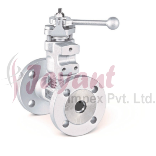
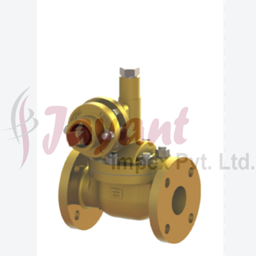

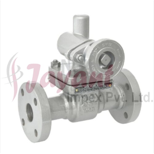


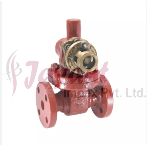

X
Blow Down Valve Price And Quantity
- 850.0 INR/Piece
- 1 Piece
Product Description
A Blowdown Valve is a highly specialized, severe-service valve used primarily in steam boiler systems, refineries, and chemical plants. Its core purpose is to remove dissolved solids, sludge, and chemical precipitates from pressurized process fluid to prevent scale formation, corrosion, and internal equipment fouling.
Because blowdown fluid contains abrasive particulate matter and drops instantly from high operating pressures to atmospheric pressure, these valves must withstand extreme velocity, flashing water, and cavitation.
Continuous vs. Intermittent Blowdown
In industrial boiler operations, blowdown is split into two distinct processes based on where the impurities gather.
[ Boiler Steam Drum ] / \ (Surface Water) (Bottom Mud Drum) │ │[ Continuous Blowdown Valve ] [ Intermittent Blowdown Valve ] (Removes dissolved solids) (Flushes heavy sludge/scale)1. Continuous Blowdown Valve (Surface Blowdown)
-
Location: Mounted near the water surface level of the steam drum.
-
Function: Continuously skims off a steady, small stream of water where the highest concentration of Total Dissolved Solids (TDS) and floating impurities accumulate.
-
Valve Design: Typically an angle needle valve or a specialized globe valve with a graduated micrometer handle (vernier scale) for micro-adjustments.
-
Trim Technology: Often uses a single-step needle trim with a venturi diffuser. As the high-pressure water flashes into steam, the wide diffuser area prevents choked flow and erosion of the body.
2. Intermittent Blowdown Valve (Bottom Blowdown)
-
Location: Connected to the lowest point of the mud drum or boiler shell.
-
Function: Opened periodically (e.g., once a shift for 1 to 2 minutes) to flush out heavy, settled suspended solids, mud, and precipitated scale that drop out of the water.
-
Valve Design: Uses specialized quick-opening levers or slow-opening seat arrangements designed to provide a sudden, high-velocity suction effect that pulls heavy sludge out.
-
Trim Technology: Uses heavy-duty multi-step pressure reducing plugs. The multi-step design splits the total pressure drop across separate internal stages. This isolates the sealing faces from the high-velocity throttling zone, ensuring tight shut-off even when handling abrasive silt.
The Two-Valve Safety Configuration
In high-pressure systems (typically over 100 PSI / 7 bar), code regulations (like ASME Section I) or engineering best practices mandate using two bottom blowdown valves in series along the same drain line for safety and wear protection:
-
The Guard / Sealing Valve: Positioned closest to the boiler. This is typically a quick-opening lever valve.
-
The Throttling / Blowing Valve: Positioned furthest from the boiler. This is typically a slow-opening seat-and-disc valve.
Standard Operating Sequence:
To Open: Open the Guard Valve (closest to boiler) first, then crack open the Blowing Valve second. The actual high-velocity fluid friction and flashing happen across the second valve, preserving the sealing surface of the first.
To Close: Close the Blowing Valve first, then close the Guard Valve second.
Material and Pressure Specifications
Standard commercial isolation valves (like general-purpose gate or ball valves) will rapidly fail if used for blowdown due to "wire-drawing" (fluid cutting paths into the seats). True blowdown valves are heavily armored:
| Parameter | Standard Engineering Specification |
| Common Sizes | DN25 to DN80 (NPS 1" to 3") |
| Pressure Classes | ASME Class 300, 600, 900 up to Class 2500 |
| Body Metallurgy | Forged Carbon Steel (ASTM A105) or Alloy Steel (ASTM A182 F11/F22) for thermal shock resistance. |
| Trim Coating | Stellite overlaid plug and seats (cobalt-chromium alloy) providing maximum hardness and resistance to particulate erosion. |
| Sealing Class | ANSI/FCI 70-2 Class IV or Class V (ensuring no energy or hot feedwater leaks out during normal operation). |
Tell us about your requirement

Price:
Quantity
Select Unit
- 50
- 100
- 200
- 250
- 500
- 1000+
Additional detail
Mobile number
Email
Name
Comapny Name
Phone Number
Email Id
City / State
Confirm Your Requirement
Verification Code
Did not receive yet?
Resend OTP

You’re Done!
We have received your requirements and will reply shortly with the best price.
Products You May Like
Other Products in 'Valves' category


×
Add a mobile number to receive call from "JAYANT IMPEX"
×
Enter OTP
×
Share additional details for a quick response
×
Thank You!
Thank You for your valuable time. We have received your details and will get back to you shortly.
×
Get a price quote for Blow Down Valve
×
JAYANT IMPEX
GST : 27AAQFJ5764L1ZJ
GST : 27AAQFJ5764L1ZJ
- 6th, 605, Majestic Shopping Center, Jagannath Shankarseth Road, Girgaon,Mumbai - 400004, Maharashtra, India
- Phone : 08045800544
- Mr Shrenik Prakash Mehta (Director)
- Mobile : 08045800544
-
jayantimpex12@gmail.com


-
Share to


Our Products
- Steel Bar
- Dowel Pins
- Industrial Bolts
- Plastic Bar
- Steel Coils
- Circle Clips
- Corten Steel Plate
- Hardox Plates
- Industrial Flanges
- Solenoid Valves
- Industrial Washer
- Fasteners
- Valves
- Industrial Fastener
- Steel Sheets And Plate
- Brass Scrap
- Bronze Scrap
- Copper Scrap
- Nickel Silver Scrap
- Nickel Copper Scrap
- Catalytic Converter Scrap
- Pipes

 Call Me Free
JAYANT IMPEX PVT. LTD. All Rights Reserved.(Terms of Use)
Developed and Managed by Infocom Network Private Limited. Terms of use | Returns Policy Member
Developed and Managed by Infocom Network Private Limited. Terms of use | Returns Policy Member
✕
Contact Us
Name
Comapny Name
Phone Number
Email Id
City / State

OTP Verification
Verification Code
Did not receive yet?
Resend OTP
Thank you!
We have received your requirements
For an immediate response, please call this
number 08045800544
✕
Tell us about your requirement
Price:
Quantity
Select Unit
Additional detail
Mobile number
Email
Name
Comapny Name
Phone Number
Email Id
City / State
Confirm Your Requirement
Verification Code
Did not receive yet?
Resend OTP
You’re Done!
We have received your requirements and will reply shortly with the best price.
Products You May Like