
 English
 Spanish
 French
 German
 Italian
 Chinese (Simplified)
 Japanese
 Korean
 Arabic
 Portuguese


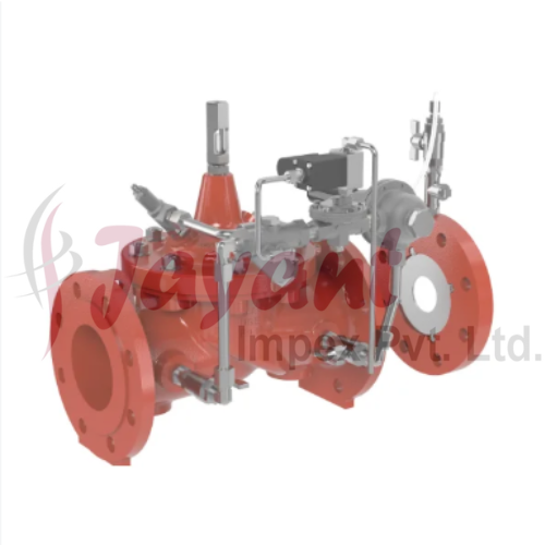


Pump Control Valves
3000.0 INR/Piece
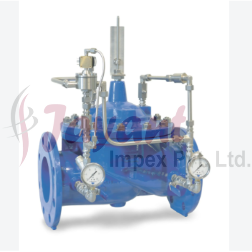
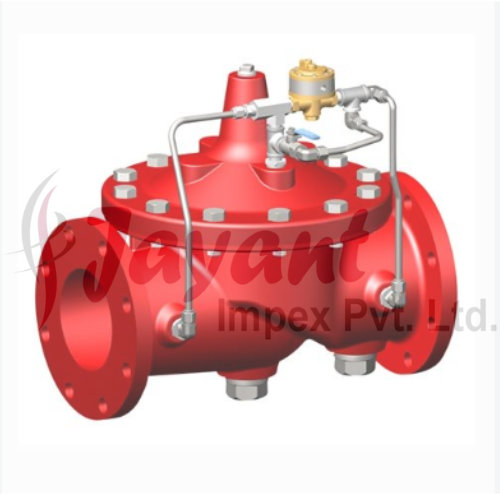
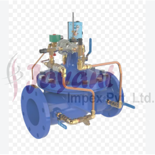
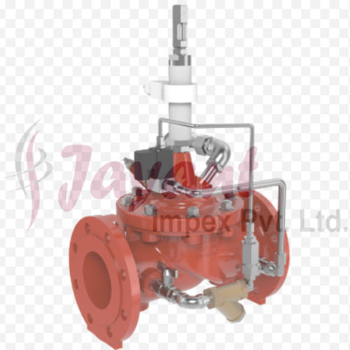
Product Details:
- Features Slow opening and closing, surge protection, noiseless operation
- Valve Type Hydraulically Actuated Valve
- Connection Type Flanged End / Screwed End
- Valve Size DN40 to DN300
- Control System Hydraulic Pilot Control
- Material Body: Ductile Iron / Cast Iron / Stainless Steel; Internals: Bronze / Stainless Steel
- Application Automatic pump control in water supply systems, irrigation, plumbing, and industrial processes
- Click to view more
X
Pump Control Valves Price And Quantity
- 1 Piece
- 3000.0 INR/Piece
Pump Control Valves Product Specifications
- Up to 16 bar
- Not Applicable (operates hydraulically)
- DN40 to DN300
- Hydraulic Pilot Control
- Hydraulic
- Flanged End / Screwed End
- -10C to 80C
- Slow opening and closing, surge protection, noiseless operation
- Hydraulically Actuated Valve
- Automatic pump control in water supply systems, irrigation, plumbing, and industrial processes
- 1 1/2 (DN40) to 12 (DN300)
- Ductile Iron / Stainless Steel
- EPDM/NBR Rubber Seals
- Body: Ductile Iron / Cast Iron / Stainless Steel; Internals: Bronze / Stainless Steel
- Water, Neutral Liquids
- Diaphragm Operated; Globe Pattern Body
- Pump Control Valve
- Fully automatic, Non-return function available
- Stainless Steel / Bronze
- 80C
- Low maintenance, easy in-line serviceability
- Horizontal or vertical mounting
- Epoxy-coated for corrosion protection
- Diaphragm type
- Clean water and compatible fluids
- 1.0 bar
- Linear and Quick Opening options available
- ISO 9001, WRAS, CE Certified
Product Description
Pump control valves are specialized, automatic valves installed directly on the discharge side of high-capacity pumps (and occasionally on the suction side). Unlike standard isolation valves, they are dynamically managedoften via hydraulic pilots, solenoids, or digital controllersto bridge the gap between pump electrical operations and pipeline fluid hydraulics.
Their primary mission is to prevent pipeline surges (water hammer) during normal pump starts and stops, and to protect the pump from destructive backflow if power fails.
1. The Core Problem They Solve
When a large centrifugal pump starts up instantly, it forces a massive column of stagnant water into motion, creating a high-pressure shockwave. Conversely, when a pump stops, the fluid column loses momentum, reverses direction, and slams back toward the pump.
If you rely solely on a standard check valve to stop this backflow, it can slam shut violently, causing a catastrophic water hammer that can rupture pipes, strip fittings, and shatter the pump casing.
2. Typical Pump Control Valve Sequences
A classic pump control valve (often a modified diaphragm globe valve or a dual-chamber plunger valve) is electrically interlocked with the pump motor starter panel to execute a controlled, multi-stage sequence.
Normal Starting Sequence
-
Pump Starts Closed: The pump motor is energized while the pump control valve remains fully closed. This allows the pump to quickly establish its head pressure without pushing against a massive, stagnant column of downstream fluid.
-
Controlled Opening: A solenoid on the valve receives a signal and slowly vents the valve's control chamber. The valve opens at a gradual, adjustable rate (e.g., over 30 to 60 seconds), gently accelerating the fluid column and preventing an initial pressure spike.
Normal Stopping Sequence
-
Valve Closes First: When a shutoff command is given, the pump motor keeps running. The valve solenoid is energized to slowly drive the valve toward a closed position.
-
Smooth Deceleration: As the valve gradually closes, it throttles the flow, safely decelerating the entire pipeline column.
-
Limit Switch Shutdown: Just as the valve reaches roughly 95% closed (where flow is negligible), an internal limit switch trips, finally de-energizing the pump motor. This eliminates shutoff water hammer completely.
3. Specialized Types of Pump Control Valves
Depending on the piping architecture, fluid medium, and pressure dynamics, different valve designs are deployed:
A. Diaphragm-Actuated Globe Valves
The most common configuration for municipal water distribution and wastewater. They utilize line pressure acting on an internal diaphragm to modulate position. They are highly customizable with hydraulic pilots to function simultaneously as pressure-sustaining or pressure-reducing valves.
B. Booster Pump Control Valves
Designed specifically for inline booster pumps. These valves feature a unique three-way solenoid control system. Instead of executing the start/stop sequence inline, they often utilize a bypass line to dump initial startup surges to an atmospheric tank or low-pressure zone before slowly closing the bypass to divert flow into the main system.
C. Deep Well Control Valves
Used in deep well turbine pump installations. When a deep well pump is off, the vertical column pipe fills with air. If the pump starts, it drives this air up at high velocity, followed by a heavy slug of water. A deep well control valve is programmed to stay open to an atmospheric vent to safely dump the high-velocity air and the initial sand/dirty water before slowly closing to direct clean water into the grid.
D. Surge Anticipator Valves
While not installed inline on the pump discharge, these are critical companions to pump systems. They are installed on a T-junction off the main line. If a sudden power failure occurs, the valve senses the immediate low-pressure wave before the destructive high-pressure return wave snaps back. It snaps open instantly, dumping fluid and breaking the force of the returning water hammer.
4. Key Material Configurations & Selection Criteria
Because pump control valves experience severe throttling and high velocity during their opening and closing cycles, they are highly prone to cavitation and erosion.
-
Body Materials: Typically Ductile Iron (ASTM A536) for standard water utility lines, Cast Steel (WCB) for industrial processes, or Super Duplex for desalination and corrosive applications.
-
Internal Trim: High-grade Stainless Steel (316 or 17-4 PH) is standard. Anti-cavitation cages or slotted plugs are frequently added if the valve must handle high differential pressures during the throttling phases.
-
Elastomers: The diaphragm and seat seals must resist compression set. EPDM is standard for water; Viton (FKM) or Buna-N are selected if hydrocarbons or elevated temperatures are present.
Advanced Corrosion-Resistant Coating
Epoxy coating is applied to all wetted surfaces of the pump control valve, safeguarding against corrosion and extending service life in even harsh environments. This ensures reliability and minimizes maintenance requirements, making it ideal for municipal and industrial applications where water quality and longevity are crucial.
Flexible Hydraulic Operation & Control
These pump control valves feature hydraulic pilot control for fully automatic operation, eliminating the need for electrical power. With diaphragm actuation and a globe pattern body structure, they offer slow opening and closing, surge protection, and noiseless flow regulation tailored to water infrastructure systems.
Robust Construction for Versatile Applications
Manufactured with a ductile iron or stainless steel body and trim options in bronze or stainless steel, these valves excel in durability. Designed for use with clean water and compatible fluids, their range from DN40 to DN300 ensures suitability for water supply, irrigation, plumbing, and process industries.
FAQ's of Pump Control Valves:
Q: How do epoxy-coated pump control valves protect against corrosion?
A: The epoxy coating forms a robust barrier on internal and external surfaces, preventing corrosive agents in water and neutral liquids from degrading the valve materials. This significantly extends the valve's lifespan, especially in environments prone to moisture and chemical exposure.Q: What installation positions are suitable for these pump control valves?
A: These valves are engineered for flexible installation and can be mounted in both horizontal and vertical positions, allowing seamless integration into a wide range of piping layouts and technical setups.Q: When should the pump control valve be used for optimal performance?
A: Ideal for systems requiring automatic regulation and protection of pumps, these valves excel in applications such as water supply networks, irrigation projects, plumbing, and industrial fluid management. Their automatic operation and non-return function ensure smooth and reliable pump cycling.Q: Where can these valves be applied effectively?
A: Their versatile design allows use in municipal water infrastructure, commercial plumbing systems, agricultural irrigation setups, and various industrial processes that utilize clean water or compatible neutral liquids within the specified pressure and temperature ranges.Q: What is the process for servicing the valve in-line?
A: Maintenance is simple due to the valve's modular structure and in-line serviceability. Routine inspection and replacement of EPDM or NBR seals, as well as stainless steel or bronze internals, can be performed without removing the valve from the pipeline.Q: What benefits does the hydraulic pilot control system provide?
A: The hydraulic pilot control system ensures precise and automatic valve operation, facilitating slow opening and closing for surge protection, noiseless flow management, and protection against water hammer effects. This safeguards pumps and pipeline systems from pressure fluctuations.Tell us about your requirement

Price:
Quantity
Select Unit
- 50
- 100
- 200
- 250
- 500
- 1000+
Additional detail
Mobile number
Email

Other Products in 'Valves' category

JAYANT IMPEX
GST : 27AAQFJ5764L1ZJ
GST : 27AAQFJ5764L1ZJ
- 6th, 605, Majestic Shopping Center, Jagannath Shankarseth Road, Girgaon,Mumbai - 400004, Maharashtra, India
- Phone : 08045800544
- Mr Shrenik Prakash Mehta (Director)
- Mobile : 08045800544
-
jayantimpex12@gmail.com


-
Share to


 Call Me Free
JAYANT IMPEX PVT. LTD. All Rights Reserved.(Terms of Use)
Developed and Managed by Infocom Network Private Limited. Terms of use | Returns Policy Member
Developed and Managed by Infocom Network Private Limited. Terms of use | Returns Policy Member
